Bidirectional synergy driving material pneumatic conveying system

A technology for pneumatic conveying and materials, applied in the direction of conveyors, transportation and packaging, etc., can solve the problems of the impact of objects to be conveyed, large pressure loss in one-way driving, slow operation, etc., to prolong the service life of equipment, increase the driving force of air pressure, The effect of slowing down the transfer speed

Active Publication Date: 2016-05-25
HUNAN SUNDY SCI & TECH DEV
View PDF14 Cites 9 Cited by
  • Summary
  • Abstract
  • Description
  • Claims
  • Application Information

AI Technical Summary

Problems solved by technology

[0005] (1) Most of the existing technologies can only be transported and driven in one direction by means of single suction or single blowing. When the distance is long or the transport drop is large, the pressure loss of the one-way drive is large, and the operation is slow and unstable. Serious Affect product reliability
[0006] (2) When the object to be conveyed in the prior art enters the receiving section of the receiving end of the pipeline, due to the large mass and high inertia of the object to be conveyed, there is a strong impact force and a lot of noise in the reception of the object to be conveyed, which is harmful to the end link and The material to be transported itself has a great influence
[0007] (3) The existing technology cannot monitor the operation of the objects to be conveyed in the transmission pipeline in real time, and because the pneumatic transmission pipeline is very long (maybe hundreds of meters), once the pressure in the transmission pipeline decreases, the objects to be conveyed will move slowly, etc. The operator cannot understand the situation at the first time. When the situation is serious, the material to be transported may stagnate in the pipeline, which has certain work risks.

Method used


Image

  • Bidirectional synergy driving material pneumatic conveying system
  • Bidirectional synergy driving material pneumatic conveying system

Examples


Embodiment Construction

[0025] The present invention will be described in further detail below in conjunction with specific embodiments and accompanying drawings.

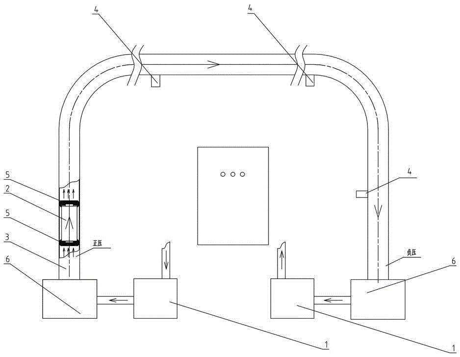
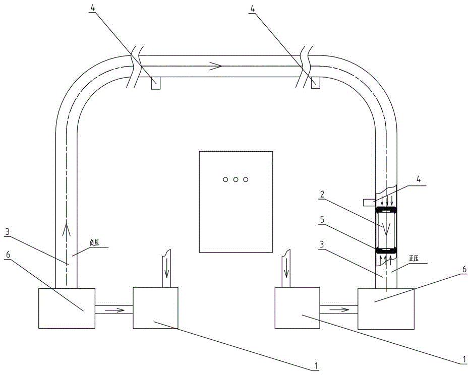
[0026] Such as figure 1 , figure 2 As shown, the present invention provides a two-way cooperatively driven material pneumatic conveying system, including a driving air source unit 1 and a transmission pipeline unit 3 for transporting the object to be conveyed 2 (in the following description, for the convenience of corresponding description, the object to be conveyed 2 An example is a sample bottle, of course, in other embodiments, the object to be conveyed 2 can also be other devices or objects to be conveyed, which should all belong to the protection scope of the present invention), and the driving air source unit 1 provides The air source driving mode of blowing or sucking air drives the pneumatic transmission of the object 2 to be conveyed. There is a driving air source unit 1 at the beginning and end of the transmission pipeline uni...


PUM


Abstract

The invention discloses a bidirectional synergy driving material pneumatic conveying system which comprises driving gas source units and a transmission pipeline unit for conveying materials to be conveyed; the driving gas source units provide a blowing or suction gas source driving mode to the inside of the transmission pipeline unit to drive the materials to be conveyed to be pneumatically transmitted; two driving gas source units are respectively arranged at an initial end and a finish end of the transmission pipeline unit; the two driving gas source units are synergically matched to provide different gas source driving modes to the inside of the transmission pipeline unit, so as to reinforce a transmission speed of the materials to be conveyed at a transmission section and/or retard the transmission speed of the materials to be conveyed at a receiving section. The bidirectional synergy driving material pneumatic conveying system has the advantages that driving modes at both ends can be flexibly converted; not only can a very strong driving force be provided at the transmission section of a pipeline, but also a receiving impact force can be buffered at the receiving section of the pipeline.

Description

technical field [0001] The invention mainly relates to the field of equipment for collecting and processing material samples, and in particular to a two-way cooperatively driven material pneumatic conveying system. Background technique [0002] For the sampling, sample preparation, and testing of material (such as ore, coal) samples, each country has mandatory standards, and the sampling and processing of samples must be carried out in accordance with the standards. The principle of sample sampling, sample preparation, and testing work process is to gradually reduce the particle size and quality of the collected samples without destroying the representativeness of the sample, until it meets the particle size and quality of the sample in the laboratory test ( Weight) accuracy requirements, and then carry out relevant laboratory analysis on the samples that meet the requirements. [0003] For example, taking coal sampling as an example, it is actually a sampling and analysis ...

Claims


Application Information

Patent Timeline
Patent Type & Authority Applications(China)
IPC IPC(8): B65G51/16B65G51/36
CPCB65G51/16B65G51/36B65G2201/0244B65G2203/025
Inventor 任率朱青刘清海王芹
Owner HUNAN SUNDY SCI & TECH DEV
Why Eureka
Try Eureka