A cloth rolling mill with hydraulically adjusted rolls

A roll and cloth technology, which is applied in the field of textile printing and dyeing equipment, can solve the problems affecting the uniformity of force on the cloth and the effect of rolling, and achieve the effects of uniform force, improved rolling effect, and compensation for deformation

Active Publication Date: 2017-11-03
林立荣
View PDF6 Cites 0 Cited by
  • Summary
  • Abstract
  • Description
  • Claims
  • Application Information

AI Technical Summary

Problems solved by technology

[0002] The existing cloth rolling mill is mainly to remove water from the cloth rolling, and now generally adopts two parallel straight rolls to carry out extrusion rolling to remove water, because both are straight rolls, when rolling, the middle part of the straight rolls will There is a slight deformation, which affects the uniformity of the force on the fabric and affects the rolling effect

Method used


Image

  • A cloth rolling mill with hydraulically adjusted rolls
  • A cloth rolling mill with hydraulically adjusted rolls
  • A cloth rolling mill with hydraulically adjusted rolls

Examples


Embodiment Construction

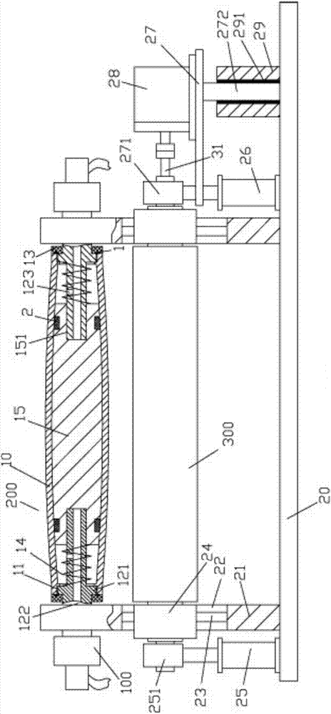
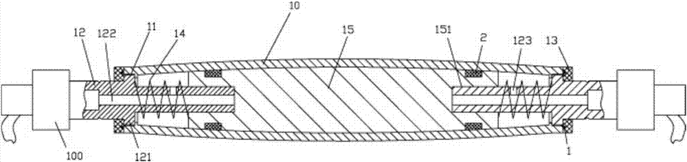
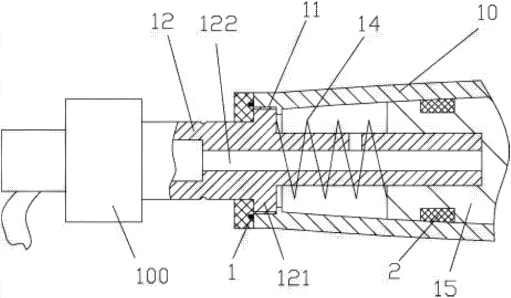
[0021] Examples, see e.g. Figure 1 to Figure 4 As shown, a cloth rolling mill with hydraulically adjusted rolls includes a roll 200 and a horizontal roll 300, the two ends of the roll 200 are hinged at the upper part of the two vertical support plates 21 of the frame 20, and the two vertical supports The bottom of the plate 21 has a moving through groove 22, and the two inner side walls of the moving through groove 22 have position-limiting protruding strips 23. In the vertical groove 241 that has on the side wall of block 24, the two ends of horizontal roller 300 are hinged on the corresponding mobile block 24, and left push oil cylinder 25 and right push oil cylinder 26 are fixed on the bottom plate of frame 20, left pushes The end of the push rod of the oil cylinder 25 is fixed with a connecting part 251, and the connecting part 251 is hinged at the left end of the horizontal roller 300. The push rod of the right push oil cylinder 26 is fixed with an adjusting plate 27, an...


PUM


Abstract

The invention discloses a fabric rolling mill with a hydraulic adjusting roller. The fabric rolling mill comprises the roller and a horizontal roll. Two ends of the roller are hinged to the upper portions of two vertical support plates of a framework, moving straight slots are formed in the lower portions of the two vertical support plates, limiting protruded strips are arranged on two inner side walls of each moving straight slot, moving blocks are inserted in the moving straight slots, the limiting protruded strips are inserted in vertical grooves in the side walls of the moving blocks, two ends of the horizontal roll are hinged onto the corresponding moving blocks, and a left pushing cylinder and a right pushing cylinder are fixed onto a bottom plate of the framework. The fabric rolling mill has the advantages that the horizontal roll can be pushed by the left pushing cylinder and the right pushing cylinder, so that the distance from the horizontal roll to the roller can be adjusted, and rolling effects can be guaranteed; the outer diameter of the outer wall of an outer rubber roller sleeve is gradually reduced from the outer wall of the middle of the outer rubber roller sleeve to two ends of the outer rubber roller sleeve, accordingly, the roller can be matched with a middle deformation position of the lower straight roll during rolling, deformation can be compensated, and uniform fabric rolling stress can be guaranteed.

Description

Technical field: [0001] The invention relates to the technical field of textile printing and dyeing equipment, in particular to a cloth rolling mill with hydraulically adjusted rolls. Background technique: [0002] The existing cloth rolling mill is mainly to remove water from the cloth rolling, and now generally two parallel straight rolls are used for squeezing and rolling to remove water. Since both are straight rolls, during rolling, the middle of the straight rolls will There is a slight deformation, which affects the uniformity of the force on the cloth and affects the rolling effect. Invention content: [0003] The purpose of the present invention is to overcome the deficiencies of the prior art and provide a distribution mill with hydraulically adjusted rolls, which pushes the horizontal rolls through the left and right push cylinders, thereby adjusting the distance between the rolls and ensuring the rolling effect , at the same time, because the diameter of the o...

Claims


Application Information

Patent Timeline
Patent Type & Authority Patents(China)
IPC IPC(8): D06B15/02
CPCD06B15/02
Inventor 林立荣
Owner 林立荣
Why Eureka
Try Eureka