Encoder and method of calculating rotational angle position

A rotation angle and encoder technology, which is applied to instruments, measuring devices, electrical devices, etc., can solve the problems of low rotation angle position accuracy, unable to fully reduce noise, etc., and achieve the effect of improving calculation accuracy.

Active Publication Date: 2016-05-25
SANKYO SEIKI MFG CO LTD
View PDF7 Cites 9 Cited by
  • Summary
  • Abstract
  • Description
  • Claims
  • Application Information

AI Technical Summary

Problems solved by technology

[0007] However, in the structure of the device described in Patent Document 1, the noise when the induced voltage (hereinafter simply referred to as the induced voltage) is s

Method used


Image

  • Encoder and method of calculating rotational angle position
  • Encoder and method of calculating rotational angle position
  • Encoder and method of calculating rotational angle position

Examples


Embodiment approach

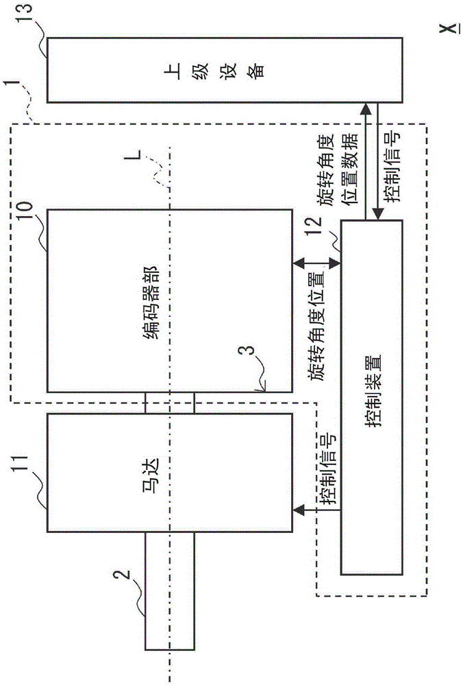
[0131] refer to figure 1 The configuration of the control system X according to the embodiment of the present invention will be described. The control system X has an encoder unit 10 , a motor 11 , a control device 12 , and host equipment 13 .

[0132] Among them, the encoder unit 10 and the control device 12 function as the encoder device 1 of the present embodiment.

[0133] The encoder unit 10 is an encoder capable of detecting a rotational angle position.

[0134] The encoder unit 10 always detects the angle of the rotating body 2 , such as a shaft having the same axis as the motor 11 , as rotation angle position data. Therefore, the encoder unit 10 has the fixed body 3 fixed to the frame of the motor 11 and the like.

[0135] The rotation angle position data includes data indicating the number of rotations of the rotating body 2 , data indicating the number of rotations of the rotating body 2 , and data indicating the angle of the rotating body 2 within one rotation. ...

Embodiment

[0348] Next, refer to Figure 9A , Figure 9B , an example of correcting the output of the encoder unit 10 in the circuit configuration of the present embodiment by the signal processing unit 100 will be described. In addition, the following Examples do not limit this invention.

[0349] Driven by other devices, the motor was rotated at a rotational speed of 5859 rpm, and the values ​​of the A-phase signal (sin) and the B-phase signal (cos) were obtained simultaneously with a period of 80 μs as the sampling period T. The angle error is calculated from the acquired Lissajous patterns of the A-phase signal and the B-phase signal. The SIN wave of one period is superimposed on the waveform of the Lissajous pattern, and the error is calculated again.

[0350] Then, the phase and amplitude of the superimposed waveform are changed, and the value with the smallest error is calculated as the generated voltage of the induced voltage.

[0351] Figure 9A As a comparative example, it...


PUM


Abstract

The invention provides an encoder and a method of calculating a rotational angle position, wherein the encoder can reduce the error for the detected rotational angle position. A signal processing unit of an encoder unit is provided with a rotational angle position calculation unit (110), a calibration scale (120) and a calibration unit (130). The rotational angle position calculation unit (110) detects the rotational angle position according to a signal of a detection element; the calibration scale (120) stores the calibrating values by enabling the calibrating values to be corresponding to the divided angle positions; the calibrating values are used for offseting the error, of the rotation speed, stacked on the signal of the detection element; the divided angle positions are divided during one circle of rotation under the specific rotation speed; and according to the calibrating values stored in the calibration scale (120), the speed and the calibration value corresponding to the divided angle are calculated.

Description

technical field [0001] The invention relates to an encoder and a calculation method for a rotation angle position. Background technique [0002] Currently, there is a device called a magnetic encoder or an optical encoder (rotary encoder) capable of detecting the rotational angle position of a shaft of a motor or the like as rotational angle position data. [0003] In addition, among encoders, there is an encoder capable of converting absolute rotational angle position data into incremental signals and the like, and transmitting the signals using two transmission lines called A phase and B phase. [0004] Here, Patent Document 1 describes an encoder technology, the encoder has a magnetic field generating unit, a base, a magnetic detection element, a set of wires, and a control unit, the magnetic field generating unit generates a magnetic field, and the base follows The detection object rotates relative to the magnetic field generation unit, the magnetic detection element is...

Claims


Application Information

Patent Timeline
IPC IPC(8): G01B7/30
Inventor 奥村宏克
Owner SANKYO SEIKI MFG CO LTD
Why Eureka
Try Eureka