Rolling bearing high speed vibration measurement device

A technology of vibration measurement and rolling bearings, applied to vibration measurement in solids, measuring devices, measuring vibration, etc., can solve the problem that the detection data cannot meet the actual work needs, and achieve the effect of flexible use and wide application range

Active Publication Date: 2016-05-25
HARBIN INST OF TECH +1
View PDF11 Cites 3 Cited by
  • Summary
  • Abstract
  • Description
  • Claims
  • Application Information

AI Technical Summary

Problems solved by technology

[0003] The purpose of the present invention is to solve the problem that the existing bearing detection is low-speed detection, and the actual working state of the bearing is usually running at high speed. The current

Method used


Image

  • Rolling bearing high speed vibration measurement device
  • Rolling bearing high speed vibration measurement device
  • Rolling bearing high speed vibration measurement device

Examples


specific Embodiment approach 1

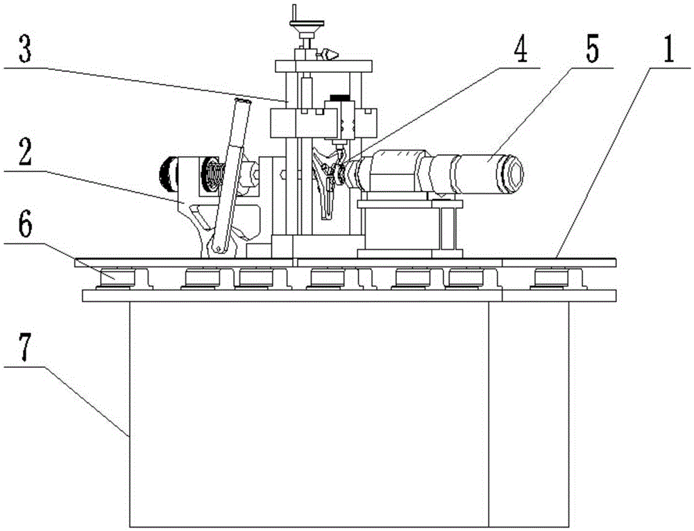
[0025] Specific implementation mode one: the following combination Figure 1 to Figure 13 Describe this embodiment, this embodiment comprises test bench 1, axial loading device 2, sensor positioning device 3, driving spindle 5 and total base 7, and described total base 7 is arranged horizontally, and described test bench 1 is arranged on total base 7 Above, the sensor positioning device 3 is arranged on the test bench 1, one side of the sensor positioning device 3 is provided with an axial loading device 2, and the other side of the sensor positioning device 3 is provided with a driving spindle 5;

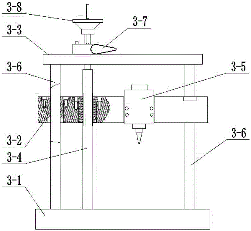
[0026] The sensor positioning device 3 includes a positioning base 3-1, a positioning beam 3-2, a beam 3-3, a lead screw 3-4, a sensor assembly 3-5 and two polished rods 3-6, and the positioning base 3-1 Fixedly connected on the test bench 1, two polished rods 3-6 are vertically arranged on the positioning base 3-1 side by side, the cross beam 3-3 is parallel to the positioning bas...

specific Embodiment approach 2

[0051] Specific implementation mode two: combination figure 1 , figure 2 and image 3 Describe this embodiment, the sensor positioning device 3 in this embodiment also includes a locking handle 3-7, the locking handle 3-7 is located on the top surface of the beam 3-3 and its grub bolt is set towards the lead screw 3-4 .

[0052] In this embodiment, the locking handle 3-7 is installed on the top surface of the crossbeam 3-3. After the positioning beam 3-2 has adjusted its position, the flat head bolt of the locking handle 3-7 withstands the lead screw 3-4, and To the effect of locking the lead screw 3-4, thereby preventing the positioning beam 3-2 from moving up and down, which is conducive to improving the positioning and detection accuracy of the sensor positioning device 3. Other unmentioned structures and connections are the same as those in the first embodiment.

specific Embodiment approach 3

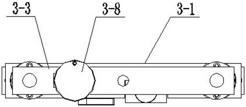
[0053] Specific implementation mode three: combination figure 2 Describe this embodiment, in this embodiment: the sensor positioning device 3 also includes two sliding bearings 3-8, the positioning beam 3-2 is processed with two through holes along its thickness direction, and each through hole is set There is a sliding bearing 3-8, and the sliding bearing 3-8 is set in one-to-one correspondence with the polished rod 3-6, and each polished rod 3-6 is installed on its corresponding sliding bearing 3-8, and the positioning beam 3-2 passes through Two sliding bearings 3-8 are slidingly matched with two polished rods 3-6. Other unmentioned structures and connections are the same as those in the second embodiment.


PUM


Abstract

The invention provides a rolling bearing high speed vibration measurement device, relating to a vibration measurement device. Existing bearing detection is low-speed detection, however a bearing actual working state is usually in a high speed operation, the grasp of bearing actual performance can not be satisfied by an existing low-speed detection method, and an actual working need can not be satisfied by the detection data. The rolling bearing high speed vibration measurement device comprises a test stand, an axial loading device, a sensor positioning device, a sensor positioning device, a driving spindle, and a master base. The master base is horizontally arranged. The test stand is arranged on the base. The sensor positioning device is arranged on the test stand. One side of the sensor positioning device is provided with an axial loading device. The other side of the sensor positioning device is provided with a driving spindle. A test bearing sleeves the driving spindle and tightly pushes the driving spindle through the axial loading device, and the detection head of the sensor assembly is close to the outer ring of the test bearing. The rolling bearing high speed vibration measurement device is used in bearing detection.

Description

technical field [0001] The invention relates to a vibration detection device, which belongs to the technical field of mechanical workpiece detection. Background technique [0002] CNC machine tools and basic manufacturing equipment are the "workhorses" of the equipment manufacturing industry. The technical level and product quality of a country's machine tool industry are important indicators to measure the development level of its equipment manufacturing industry. At present, in order to obtain higher production efficiency and higher processing quality, high-speed machining technology is widely used, and the key component to realize high-speed, high-reliability, and high-precision processing machine tools is the electric spindle, the key to realizing high-speed electric spindle The component is the bearing. At present, the dm·n value of the grease-lubricated grinding electric spindle has reached as high as 1.56×10⁶mmr / min, which has high requirements on the performance of t...

Claims


Application Information

Patent Timeline
IPC IPC(8): G01H1/00
CPCG01H1/003
Inventor 王黎钦古乐侯萍萍柏迎村雷军
Owner HARBIN INST OF TECH
Why Eureka
Try Eureka