Vibration detection device and abnormal judgment system

A technology for vibration detection and abnormal judgment, which is applied in the direction of measurement devices, vibration measurement in fluids, and measurement vibrations. It can solve the problems of inability to check rotating machinery in real time and long processing time, and achieve real-time detection and shorten the time.

Active Publication Date: 2022-06-03
MITSUBISHI ELECTRIC ENG CO LTD
View PDF6 Cites 0 Cited by
  • Summary
  • Abstract
  • Description
  • Claims
  • Application Information

AI Technical Summary

Problems solved by technology

[0010] In addition, there is a problem that the rotating machinery cannot be inspected in real time while the above arithmetic processing is performed because the envelope processing and FFT require a long processing time.

Method used


Image

  • Vibration detection device and abnormal judgment system
  • Vibration detection device and abnormal judgment system
  • Vibration detection device and abnormal judgment system

Examples


Embodiment approach 1

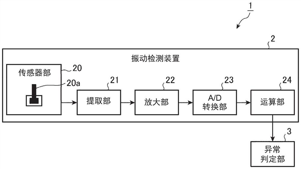
[0030] The extraction unit 21 extracts the oscillation signal of the resonance frequency of the sensor unit 20. For example, the extraction unit 21 uses an extraction cantilever

[0031] The amplification unit 22 amplifies the amplitude of the oscillation signal extracted by the extraction unit 21. For example, the amplifying part 22 passes

[0032] The A / D converter 23 converts the oscillation signal whose amplitude is amplified by the amplifier 22 into a digital signal. For example, A / D to

[0033] The calculation section 24 evaluates the temporal change of the oscillation signal after being converted into a digital signal by the A / D conversion section 23

[0035] The abnormality determination unit 3 determines the abnormality of the rotating machine based on the evaluation value calculated by the vibration detection device 2. E.g,

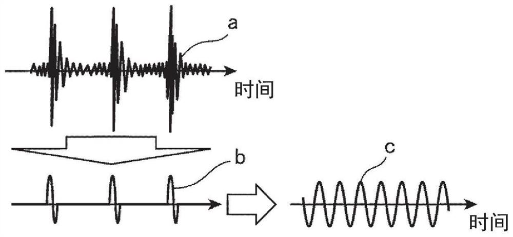
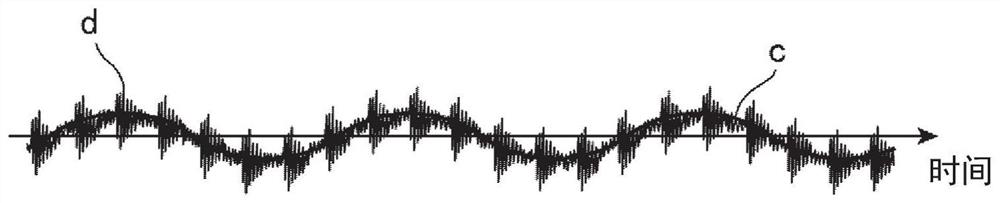
[0037] Next, the operation of the sensor unit 20 will be described.

[0039] In FIG. 2, the AE waveform a is the waveform of the AE wave generat...

Embodiment approach 2

[0066] In addition, the above-mentioned determination result output from the comparison unit 26 becomes the evaluation standard of the vibration generated by the rotating machine,

[0067] In addition, the sensor unit 20 may have a structure including a plurality of cantilevers having different resonance frequencies. by having multiple

[0069] In FIG. 7 , the relationship between the oscillation amplitude and the rotational speed of the first cantilever 20a is set as A1, and the oscillation of the second cantilever 20a is set as A1.

[0071] In addition, when the sensor unit 20 includes a plurality of cantilevers 20a having different resonance frequencies, as shown in FIG. 8, it is possible to obtain


PUM


Abstract

The sensor unit (20) has an oscillation structure that oscillates using vibration waves generated by the rotation of the rotary machine. An extraction unit (21) extracts an oscillation signal of a resonance frequency of the sensor unit (20). The amplification unit (22) amplifies the oscillation signal extracted by the extraction unit (21). The A / D converter (23) converts the amplified oscillation signal into a digital signal. A calculation unit (24) calculates an evaluation value representing a temporal change of the oscillation signal converted into a digital signal.

Description

Vibration detection device and abnormality determination system technical field The present invention relates to a vibration detection device for detecting vibration generated by the rotation of a rotating machine, and a device equipped with An abnormality determination system of the vibration detection device. Background technique [0002] Conventionally, there has been proposed a method of judging the Unusual device. For example, the vibration inspection device described in Patent Document 1 is based on the detection of The power spectrum obtained by frequency analysis of the intensity of the vibration is used to obtain the corresponding frequency components related to the vibration. power spectrum and calculate statistics. The rotating part is a rotating machine with a rotating mechanism, and the sensor detects that the rotating part is vibration generated by the rotation. The statistic is the root mean square, arithmetic mean, maximum value, etc. of the power...

Claims


Application Information

Patent Timeline
Patent Type & Authority Patents(China)
IPC IPC(8): G01H17/00G01M99/00
CPCG01H3/12G01M13/028
Inventor 篠原慎二波多野照
Owner MITSUBISHI ELECTRIC ENG CO LTD
Why Eureka
Try Eureka