Flexible circuit board

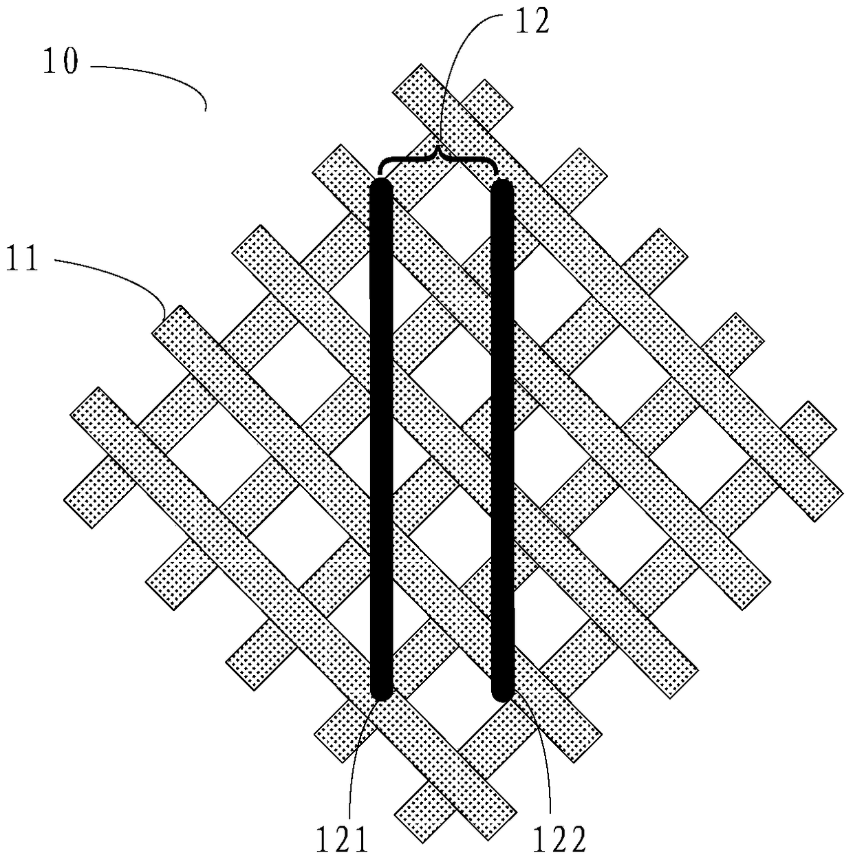
A flexible circuit board and metal layer technology, applied in the electronic field, can solve problems such as increased signal transmission delay, impedance difference, and different areas of reference layer ground wires 11

Active Publication Date: 2018-11-16
WUHAN TIANMA MICRO ELECTRONICS CO LTD
View PDF11 Cites 0 Cited by
  • Summary
  • Abstract
  • Description
  • Claims
  • Application Information

AI Technical Summary

Problems solved by technology

from figure 1 It can be seen from the figure that since the positions of the signal line 121 and the signal line 122 relative to the reference layer ground line 11 are inconsistent, their areas relative to the reference layer ground line 11 are also different, which will result in two signal lines 121 There is an impedance difference between 122 and 122, which will increase the transmission delay of the signal on the differential signal line pair 12, and affect the stability of high-speed signal transmission

Method used


Image

  • Flexible circuit board
  • Flexible circuit board
  • Flexible circuit board

Examples


Embodiment Construction

[0011] The application will be further described in detail below with reference to the drawings and embodiments. It can be understood that the specific embodiments described here are only used to explain the related invention, but not to limit the invention. In addition, it should be noted that, for ease of description, only the parts related to the relevant invention are shown in the drawings.

[0012] It should be noted that the embodiments in the application and the features in the embodiments can be combined with each other if there is no conflict. Hereinafter, the present application will be described in detail with reference to the drawings and in conjunction with embodiments.

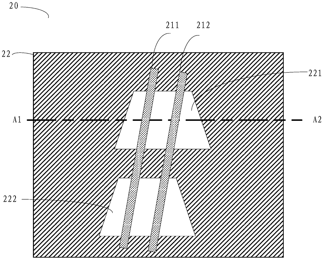
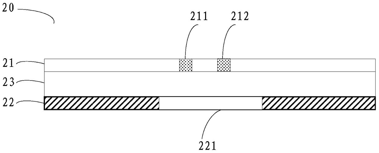
[0013] Please refer to Figure 2A with Figure 2B , Which shows a schematic structural diagram of an embodiment of the flexible circuit board of the present application. Figure 2A Is a top view of the flexible circuit board 20 of this embodiment, Figure 2B Yes Figure 2A A cross-sectional view of...


PUM


Abstract

The embodiment of the present application discloses a flexible circuit board, including: a first metal layer, a second metal layer, and a flexible substrate arranged between the first metal layer and the second metal layer; At least one pair of differential signal lines is provided; a plurality of hollow patterns are arranged in the second metal layer, and the hollow patterns have at least two relatively parallel sides; in one of the hollow patterns, only the relatively parallel The two sides of are intersected by a pair of said differential signal lines. The embodiments of the present application can reduce impedance differences of differential signal lines.

Description

Technical field [0001] This application relates to the field of electronic technology, in particular to the field of circuit technology, and in particular to a flexible circuit board. Background technique [0002] Flexible Printed Circuit Board (FPC) is a printed circuit made of a flexible insulating substrate. It has the advantages of high wiring density, light weight, thin thickness, and good flexibility, so it has a wide range of applications in the electrical field. Applications. The multi-layer FPC may include a signal layer for transmitting signals and a reference ground used as a reference plane, and a pair of differential signal lines may be arranged in the signal layer for transmitting high-speed signals. [0003] In the prior art, although the differential signal line can improve the anti-interference ability of signal transmission and accurately control the signal timing to a certain extent, the differential signal line is difficult to be uniformly arranged on the refer...

Claims


Application Information

Patent Timeline
Patent Type & Authority Patents(China)
IPC IPC(8): H05K1/02
CPCH05K1/0228
Inventor 陈珑周会娟谭绿水戴超
Owner WUHAN TIANMA MICRO ELECTRONICS CO LTD
Why Eureka
Try Eureka