Printed circuit board

A printed circuit board and circuit board technology, which is applied in the direction of measuring electricity, measuring electrical variables, measuring devices, etc., can solve problems such as the influence of unstable test results

Inactive Publication Date: 2016-10-19
HONG FU JIN PRECISION IND (SHENZHEN) CO LTD +1
View PDF0 Cites 0 Cited by
  • Summary
  • Abstract
  • Description
  • Claims
  • Application Information

AI Technical Summary

Problems solved by technology

Usually the test circuit board used by testers needs to be modified on the basis of the main board to be tes

Method used


Image

  • Printed circuit board
  • Printed circuit board
  • Printed circuit board

Examples


Embodiment Construction

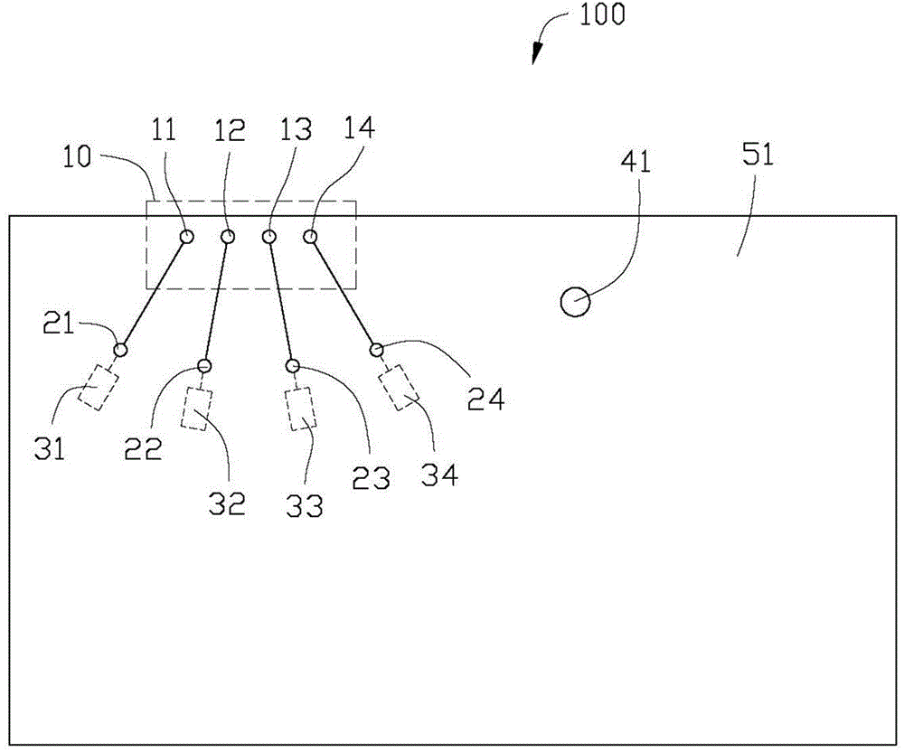
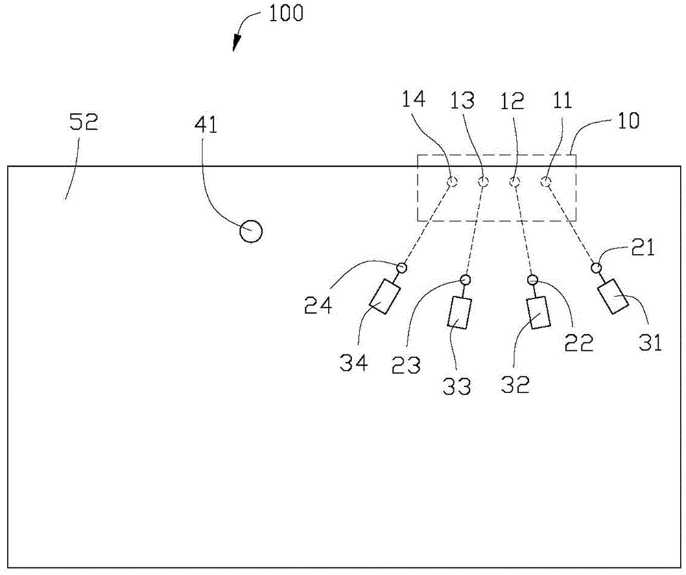
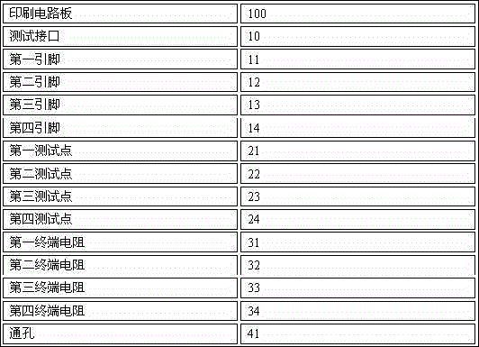
[0012] Please refer to figure 1 and figure 2 , the printed circuit board 100 of the present invention includes several test interfaces, taking the test interface 10 as an example, the test interface 10 includes a first pin 11 , a second pin 12 , a third pin 13 and a fourth pin 14 . The first pin 11 is sequentially connected to a first test point 21 and a first terminal resistor 31 through a wire, and the second pin 12 is sequentially connected to a second test point 22 and a second terminal resistor 32 through a wire, The third pin 13 is sequentially connected to a third test point 23 and a third terminal resistor 33 through wires, and the fourth pin 14 is sequentially connected to a fourth test point 24 and a fourth terminal resistor 34 through wires. The first pin 11, the second pin 12, the third pin 13 and the fourth pin 14 are respectively connected with the first test point 21, the second test point 22, the third test point 23 and the fourth test point 24 The distances...


PUM


Abstract

A printed circuit board comprises at least one testing interface. The testing interface comprises a plurality of pins. Each pin is connected with a terminal resistor through a testing point. The distances between the legs and corresponding testing points are same. According to the printed circuit board, circular testing points and cement terminal resistors are used; and in testing, discharging of a static gun is utilized for realizing smoother receiving energy of the printed circuit board. Furthermore a testing result influence caused by gap discharging can be prevented. Testing accuracy and testing stability can be effectively improved.

Description

technical field [0001] The invention relates to a printed circuit board. Background technique [0002] During the electromagnetic interference test, it is necessary to test and record the working condition of each pin of the motherboard interface when the current is injected, so as to test the maximum current value that each pin can withstand. Usually, the test circuit board used by testers needs to be modified on the basis of the main board to be tested for testing, and the instability of the modification process will have a very large impact on the test results. Contents of the invention [0003] In view of this, it is necessary to provide a printed circuit board that can effectively improve the test accuracy and stability. [0004] A printed circuit board comprising: [0005] At least one test interface, the test interface includes several pins, each pin is connected to a terminal resistance through a test point, and the distance from each pin to the corresponding tes...

Claims


Application Information

Patent Timeline
IPC IPC(8): G01R31/00
Inventor 龙贤霈吁武哲
Owner HONG FU JIN PRECISION IND (SHENZHEN) CO LTD
Why Eureka
Try Eureka