Resonant circuit control method, power supply circuit and charging pile

A resonant circuit and power circuit technology, applied in control/regulation systems, high-efficiency power electronic conversion, electrical components, etc., can solve the problem of unbalanced heat distribution, and achieve the effect of avoiding temperature difference, achieving uniform heat distribution and loss

Inactive Publication Date: 2019-08-16
XIAN TGOOD INTELLIGENT CHARGING TECH CO LTD
View PDF5 Cites 0 Cited by
  • Summary
  • Abstract
  • Description
  • Claims
  • Application Information

AI Technical Summary

Problems solved by technology

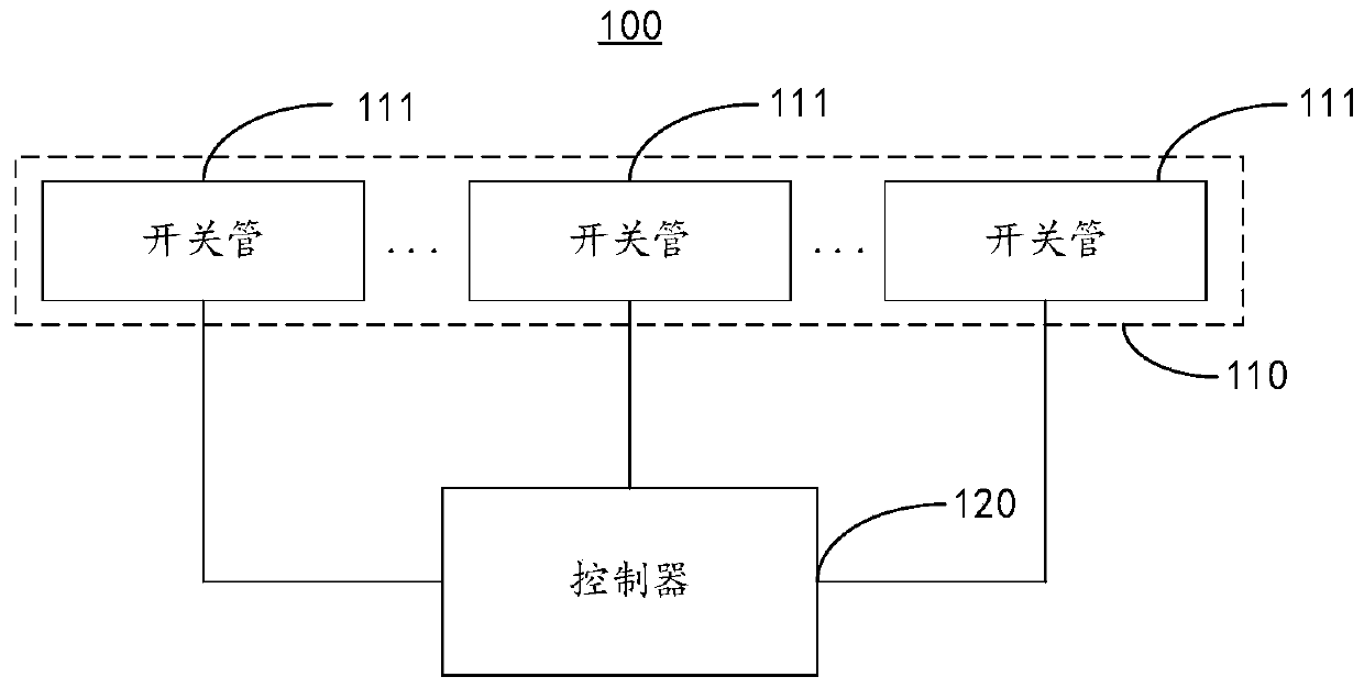
[0005] The purpose of this application is to provide a resonant circuit control method, power circuit and charging pile to solve the problem of unbalanced heat distribution caused by different power device losses in the resonant circuit

Method used


Image

  • Resonant circuit control method, power supply circuit and charging pile
  • Resonant circuit control method, power supply circuit and charging pile
  • Resonant circuit control method, power supply circuit and charging pile

Examples


Embodiment Construction

[0026] In order to make the purposes, technical solutions and advantages of the embodiments of the present application clearer, the technical solutions in the embodiments of the present application will be clearly and completely described below in conjunction with the drawings in the embodiments of the present application. Obviously, the described embodiments It is a part of the embodiments of this application, not all of them. The components of the embodiments of the application generally described and illustrated in the figures herein may be arranged and designed in a variety of different configurations.

[0027] Accordingly, the following detailed description of the embodiments of the application provided in the accompanying drawings is not intended to limit the scope of the claimed application, but merely represents selected embodiments of the application. Based on the embodiments in this application, all other embodiments obtained by persons of ordinary skill in the art w...


PUM


Abstract

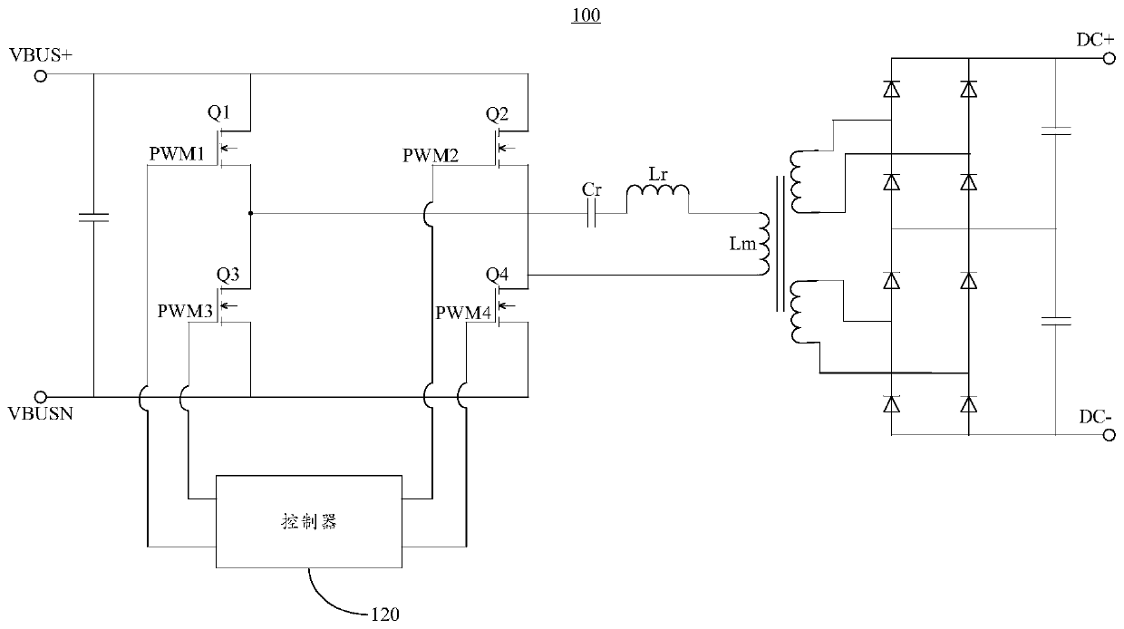
The invention provides a resonant circuit control method, a power supply circuit and a charging post, and relates to the technical field of charging. Since a preset wave emitting time period comprisesadjacent first time period and second time period and the first time period and the second time period are associated with the physical heat dissipation of a plurality of switch tubes in a resonant circuit, frequency modulation waves and width modulation waves are alternately outputted to each switch tube in the wave emitting time period according to the first time period and the second time period, each switch tube can receive both the frequency modulation waves and the width modulation waves in each wave emitting time period, the alternating output of the frequency modulation waves and thewidth modulation waves is achieved, in this way, the turn-off current of each switch tube can also achieve the alternating of large turn-off current and small turn-off current, so that the losses of all the switch tubes are substantially the same, therefore, a large temperature difference generated in the resonant circuit is avoided, and the effect of equalized heat distribution is achieved.

Description

technical field [0001] The present application relates to the technical field of charging, in particular, to a method for controlling a resonant circuit, a power circuit and a charging pile. Background technique [0002] With the development of charging technology, higher conversion efficiency and wider output voltage range have become an inevitable trend for charging modules to meet the needs of the charging industry. [0003] In order to achieve higher conversion efficiency, the LLC (abbreviation of Lr, Lm, Cr, which respectively represent the resonant inductance, excitation inductance and resonant capacitor in the resonant parameters) topology is widely used in the design of the charging module. Due to the narrow high-efficiency working range of the LLC topology, it is difficult to achieve high conversion efficiency at low-voltage output and light-load output within a wide range of output voltage and output current in the charging field. [0004] In the existing solution...

Claims


Application Information

Patent Timeline
Patent Type & Authority Applications(China)
IPC IPC(8): H02M3/335
CPCH02M3/33569Y02B70/10
Inventor 李雄郭进石浩
Owner XIAN TGOOD INTELLIGENT CHARGING TECH CO LTD
Why Eureka
Try Eureka