Automatic Spot Welding Diaphragm Machine

An automatic spot welding and diaphragm technology, applied in welding equipment, resistance welding equipment, welding/welding/cutting items, etc., can solve the problems of poor consistency, affecting product performance, and the product qualification rate cannot reach 100%, Achieve the effect of ensuring consistent quality and performance, maintaining consistency and reliability, and reducing the risk of customer complaints

Active Publication Date: 2019-02-01
BESTAR HLDG
View PDF7 Cites 1 Cited by
  • Summary
  • Abstract
  • Description
  • Claims
  • Application Information

AI Technical Summary

Problems solved by technology

[0002] When spot welding the diaphragm: After training the personnel and setting the parameters of the spot welding machine, the air pressure, and the position of the tooling, due to the differences in each operation of the personnel and the stability of the equipment, the product performance varies greatly. Large, poor consistency;
[0003] At present, the most commonly used manual spot welding diaphragm method, the main problem of this method is that the human factor is relatively large, the responsibility, proficiency, strength and speed of spot welding have a direct impact on the operation, and the waste of personnel is relatively large; And there is also the possibility that the quality of the diaphragm and the diaphragm are not concentric, the possibility of skewing, the deformation of the diaphragm, and the impact on product performance. The demand for human resources is relatively large, at least 4 to 5 manpower is required, and because of the equipment The influence of stability and human factors will lead to the problem that the qualified rate of the product cannot reach 100%

Method used


Image

  • Automatic Spot Welding Diaphragm Machine
  • Automatic Spot Welding Diaphragm Machine
  • Automatic Spot Welding Diaphragm Machine

Examples


Embodiment Construction

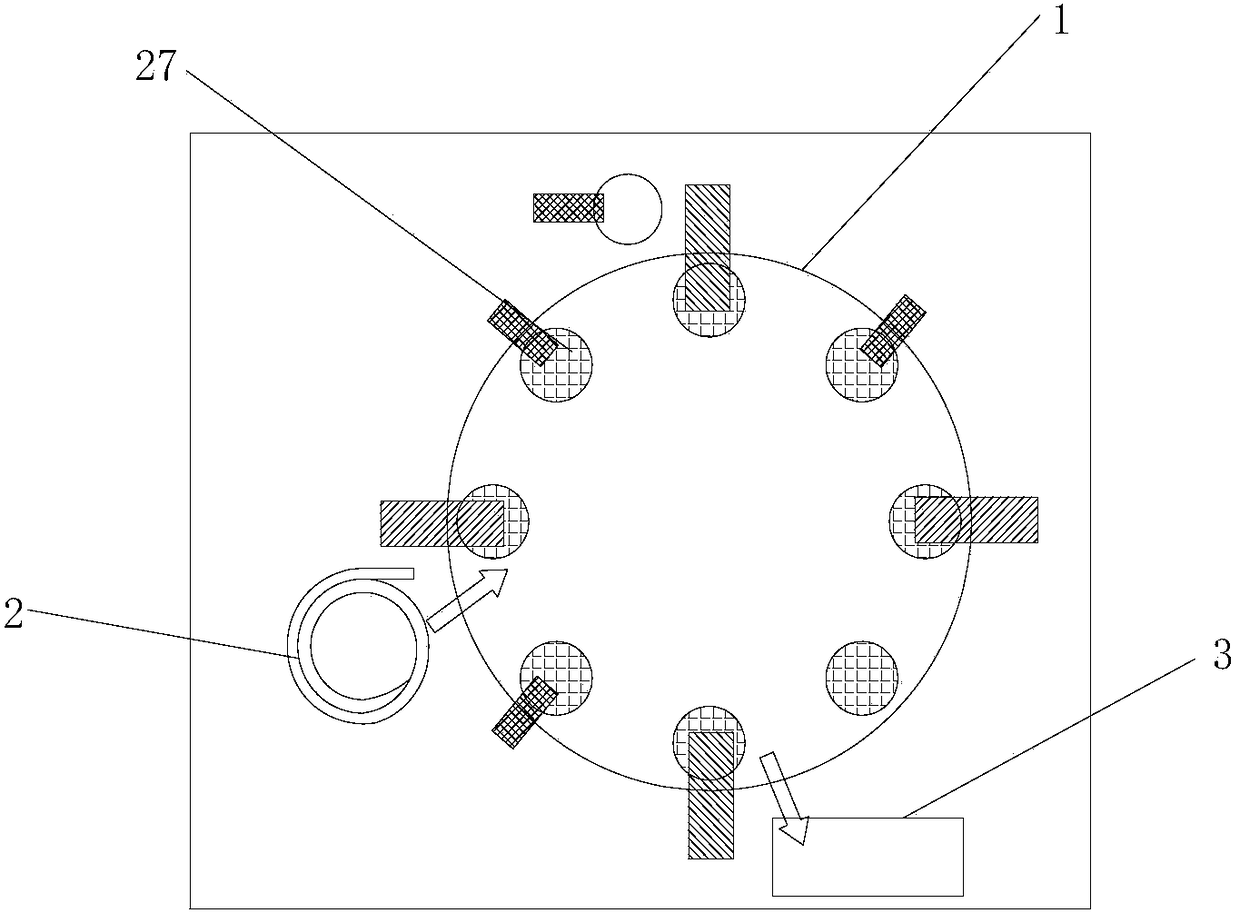
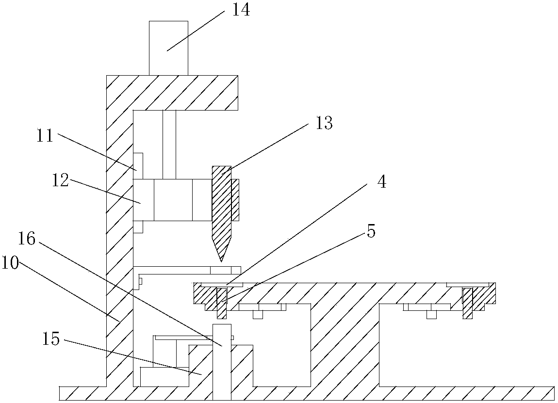
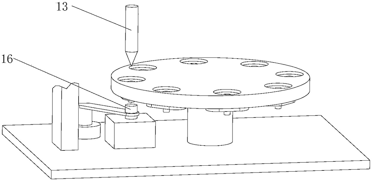
[0021] see figure 1 As shown, the automatic spot welding diaphragm machine is characterized in that it includes a rotating disk 1 arranged on the workbench and a first feeding device, a second feeding device, a spot welding device and a rotating disk clockwise arranged on the working table. Unloading device; at least one circulation tool is evenly distributed on the outer peripheral surface of the turntable; the first feeding device includes a shaker tray 2, a push-out cylinder and a first manipulator; the second feeding device includes a diaphragm placement device and the second manipulator used in conjunction with the film placement device; the unloading device includes a receiving box 3 and a third manipulator; the flow transfer tool includes a placement groove 4 arranged on the turntable, and the placement groove is provided with copper core 5;

[0022] The diaphragm placement device includes a base 7 with a jack, in which a "T" shaped diaphragm tooling 8 is arranged, and...


PUM


Abstract

The invention relates to the technical field of membrane machines, in particular to an automatic membrane spot welding machine. Circulation tools comprise containing grooves formed in a rotating plate, and copper cores are arranged in the containing grooves; a membrane placement device comprises a base with an insertion hole, a T-shaped membrane tool is arranged in the insertion hole, and a motor is arranged in the insertion hole in the bottom end of the membrane tool; the drive end of the motor makes contact with a membrane at the bottom end of the membrane tool; a spot welding device comprises a first support arranged on a work table, a sliding rail vertically arranged at the top end of the first support, a sliding block arranged on the sliding rail and a top electrode installed on the sliding block; a first air cylinder pushing the sliding block to be lifted is arranged at the top end of the first support; a supporting column is arranged at the part, below the top electrode, of the work table and is provided with a bottom electrode capable of being lifted. The automatic membrane spot welding machine can accurately guarantee the quality of vibration membranes, keep the uniformity and the reliability of the vibration membranes, avoid the phenomenon that mass slices and the membranes are not concentric in production and improve the stability of products.

Description

technical field [0001] The invention relates to the technical field of diaphragm machines, in particular to an automatic spot welding diaphragm machine. Background technique [0002] When spot welding the diaphragm: After training the personnel and setting the parameters of the spot welding machine, the air pressure, and the position of the tooling, due to the differences in each operation of the personnel and the stability of the equipment, the product performance varies greatly. Large, poor consistency; [0003] At present, the most commonly used manual spot welding diaphragm method, the main problem of this method is that the human factor is relatively large, the responsibility, proficiency, strength and speed of spot welding have a direct impact on the operation, and the waste of personnel is relatively large; And there is also the possibility that the quality of the diaphragm and the diaphragm are not concentric, the possibility of skewing, the deformation of the diaph...

Claims


Application Information

Patent Timeline
Patent Type & Authority Patents(China)
IPC IPC(8): B23K11/11B23K11/36B23K101/18
CPCB23K11/0026B23K11/115B23K11/36B23K2101/18
Inventor 常琦陶红仲张秀琴李红元
Owner BESTAR HLDG
Why Eureka
Try Eureka