
Flow calibration device for methane conveying pipeline

A technology for gas transmission pipeline and calibration device, which is applied in the energy field to achieve the effects of simple equipment, avoiding cumbersome procedures, and stable and reliable effects.

Inactive Publication Date: 2016-06-01
BIOGAS SCI RES INST MIN OF AGRI
View PDF7 Cites 1 Cited by
  • Summary
  • Abstract
  • Description
  • Claims
  • Application Information

AI Technical Summary

Problems solved by technology

[0003]The purpose of this invention is to overcome the defects of the existing flowmeter calibration equipment, which are cumbersome, labor-intensive, time-consuming, and affect the normal operation of biogas projects, and provide people with A biogas pipeline flow calibration device with simple equipment, good sealing performance, convenient operation, stable and reliable effect

Method used


Image

  • Flow calibration device for methane conveying pipeline

Examples


Embodiment 1

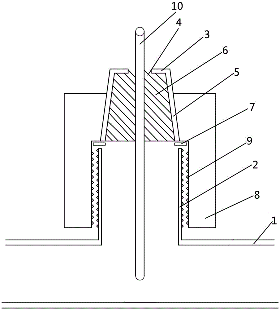
[0020] The biogas pipeline flow calibration device in this example is as follows: figure 1 As shown, it is mainly composed of a pipeline wind speed sensor 10, a rubber plug 6, a tapered sleeve 5 and a nut 8. It is characterized in that the pipeline wind speed sensor 10 is inserted into the rubber plug 6, and the rubber plug 6 is installed in the tapered sleeve 5. The tapered The sleeve 5 is fixed on the reserved orifice 2 of the biogas pipeline 1 through a nut 8 .

[0021] A limiting plate 3 is arranged on the conical sleeve 5 to limit the position of the rubber stopper 6 .

[0022] A sensor hole 4 is opened on the limiting plate 3 .

[0023] The nut 8 is connected to the reserved hole 2 through the thread 9, and a sealing gasket 7 is arranged at the joint between the nut 8 and the reserved hole 2.

[0024] The specific operation is as follows:

[0025] After punching a hole in the center of the rubber stopper 6, insert the tapered sleeve 5 from the lower end of the nut 8,...


PUM


Abstract

The invention relates to a flow calibration device for a methane conveying pipeline and belongs to the field of energy.The flow calibration device is composed of a pipeline air velocity transducer 10, a rubber plug 6, a conical sleeve 5 and a nut 8.The pipeline air velocity transducer 10 is inserted into the rubber plug 6, the rubber plug 6 is arranged in the conical sleeve 5, and the conical sleeve 5 is fixed to a reserved hole 2 of the methane pipeline 1 through the nut 8.The defects that existing flow meter calibration equipment is complex in calibration process, large in consumed labor and long in consumed time, and affects normal operation of a methane project are overcome, and the provided flow calibration device for the methane conveying pipeline is simple in equipment, good in sealing performance, convenient and rapid to operate and stable and reliable in effect.

Description

Technical field: [0001] The invention belongs to the field of energy, and in particular relates to a device for calibrating the flow of a biogas transmission pipeline. Background technique: [0002] Biogas flow meters have been installed in existing biogas projects, but the detection of gas production in biogas projects should use calibrated or calibrated instruments and meters to facilitate the traceability of the value. The existing flowmeter calibration equipment does not aim at the non-destructive calibration of the flowmeter under the pressure of 4000-10000Pa in the biogas pipeline, but needs to close the valve - stop the gas transmission - cut off the pipeline - install the flowmeter - test completed - stop the gas transmission - unload Flow meter - Connect the pipe. The existing calibration process is cumbersome, and the installation and disassembly of the flowmeter is labor-intensive and time-consuming. It is necessary to stop the gas transmission twice, which aff...

Claims


Application Information

Patent Timeline
Patent Type & Authority Applications(China)
IPC IPC(8): G01F25/00
CPCG01F25/15
Inventor 冉毅丁自立李谦彭德全王超
Owner BIOGAS SCI RES INST MIN OF AGRI
Learn More