A performance testing device for flue gas pollution control equipment

A technology for pollution control and equipment performance, applied in measuring devices, sampling devices, analyzing gas mixtures, etc., to achieve the effects of convenient processing and installation, strong adaptability, and large coverage area

Active Publication Date: 2018-07-24
DATANG ENVIRONMENT IND GRP
View PDF11 Cites 0 Cited by
  • Summary
  • Abstract
  • Description
  • Claims
  • Application Information

AI Technical Summary

Problems solved by technology

[0004] In view of the deficiencies in the performance evaluation methods of existing smoke pollution control devices, the purpose of the present invention is to provide a performance detection device for smoke pollution control equipment, which can accurately measure the effect of the smoke pollution control device and monitor the operation of the device in real time

Method used


Image

  • A performance testing device for flue gas pollution control equipment
  • A performance testing device for flue gas pollution control equipment
  • A performance testing device for flue gas pollution control equipment

Examples


example 1

[0043]Specific measurement example 1: evaluate the overall performance of pollutant treatment equipment.

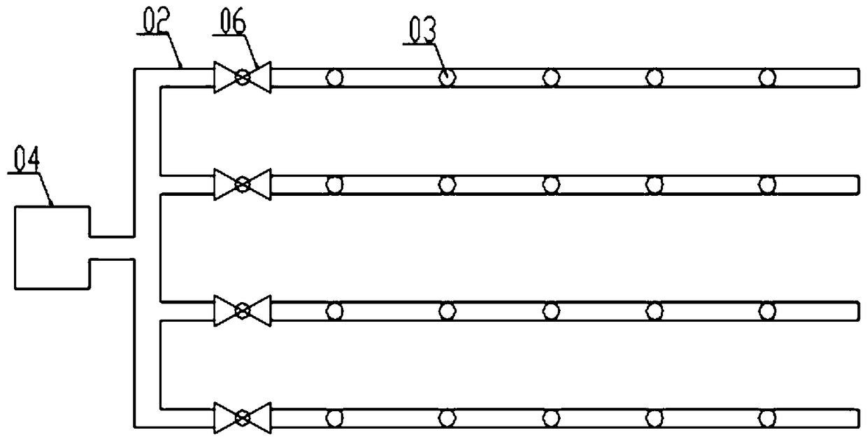
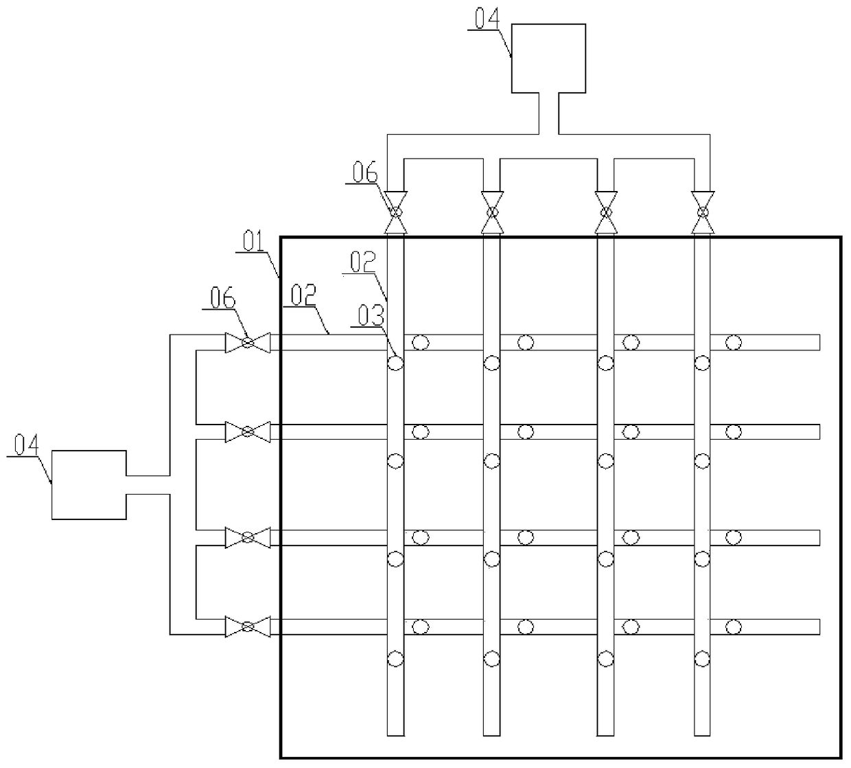
[0044] Taking the SCR denitrification reactor as an example, the sampling pipelines are arranged at the inlet and outlet of the SCR denitrification reactor respectively, and the arrangement is as follows: figure 2 , Figure 4 shown. Each group is provided with 4 sub-pipelines, and the numbers of the sub-pipelines crossed are A, B, C, D (the upper sampling line at the inlet and the upper sampling line at the outlet) and a, b, c, d (inlet The lower sampling line at the outlet and the lower sampling line at the outlet). When sampling and measuring, the flue gas composition at each sub-pipeline position is measured by opening and closing the control valve of the corresponding pipeline. Table 1 shows the measurement results of the inlet and outlet of the SCR denitration reactor:

[0045] Table 1 Overall performance evaluation of SCR denitration reactor measurement results...

specific Embodiment 2

[0049] Specific embodiment two: judging the fault area of ​​the pollutant treatment equipment.

[0050] The catalyst in the middle area of ​​a certain SCR denitrification reactor is partially deactivated, and its inlet and outlet are equipped with an ordinary flue gas composition measuring device. The measuring point is single and the length of entering the reactor is insufficient. The results are shown in Table 2:

[0051] Table 2 Measurement results of SCR denitrification reactor Common measuring device

[0052] NOx concentration

Ordinary measuring device mg / Nm 3

Entrance

332

Export

47

Denitrification efficiency

85.8%

[0053] It can be seen from the above table that although the catalyst in the middle area of ​​the reactor is partially deactivated, this operation problem cannot be detected in time through the measurement results of the flue gas composition.

[0054] The reactor is equipped with the flue gas composition...


PUM

PropertyMeasurementUnit
areaaaaaaaaaaa
denitrification rateaaaaaaaaaa

Abstract

The invention aims to provide a smoke pollution treatment equipment performance detection device which comprises two sampling pipeline groups respectively extending into an equipment front flue and an equipment rear flue partly. Each sampling pipeline group comprises two sampling pipelines which are arranged in a crossed manner, each sampling pipeline comprises a main pipeline and multiple branched pipelines communicated with the main pipeline, a control valve is arranged on each branched pipeline which is provided with multiple sampling holes, a cross section where any sampling pipeline is positioned comprises multiple equal-area regions, a sampling hole formed in one sampling pipeline and a shadow of a sampling hole formed in another sampling pipeline are formed in the corresponding equal-area region, each sampling hole or the shadow of the same is located at a position close to the center of one equal-area region, and each sampling pipeline is connected with a smoke ingredient collecting and measuring unit. The device can accurately measure effect of a smoke pollution prevention and control device and monitor running conditions of the smoke pollution prevention and control device in real time.

Description

technical field [0001] The invention relates to the technical field of flue gas component measurement, in particular to a performance detection device for flue gas pollution control equipment. Background technique [0002] As my country's air pollution situation is becoming increasingly severe and air pollution prevention and control standards are becoming more and more stringent, the country's requirements for air pollution control equipment are gradually increasing. In the field of air pollution prevention and control in thermal power plants, the current common flue gas pollution control equipment includes SCR denitrification reactor, electric / bag filter, desulfurization equipment, etc. How to accurately measure the treatment effect of flue gas pollution control equipment and monitor the equipment in real time The operation situation is an important issue under the current severe situation of air pollution prevention and control. [0003] At present, the real-time monitor...

Claims


Application Information

Patent Timeline
Patent Type & Authority Patents(China)
IPC IPC(8): G01N33/00G01N1/22
CPCG01N1/2258G01N33/0004
Inventor 李春雨李穹马务赵宇明孟磊陶君邹红果
Owner DATANG ENVIRONMENT IND GRP
Why Eureka
Try Eureka