Electric power connection fitting for overhead line

A technology for connecting fittings and overhead lines. It is used in overhead installation, electrical components, cable installation, etc. It can solve the problems of easy loosening and poor firmness, and achieve the effect of ensuring working performance, ensuring stability and reliability, and excellent anti-loosening effect.

Inactive Publication Date: 2016-06-01
胡妍
View PDF0 Cites 0 Cited by
  • Summary
  • Abstract
  • Description
  • Claims
  • Application Information

AI Technical Summary

Problems solved by technology

However, the traditional power line connection fittings also have shortcomings. The pressure of the clamping line depends on the pressure of the ordinary bolt assembly, which is poor in firmness and easy to loosen.

Method used


Image

  • Electric power connection fitting for overhead line
  • Electric power connection fitting for overhead line
  • Electric power connection fitting for overhead line

Examples


Embodiment 1

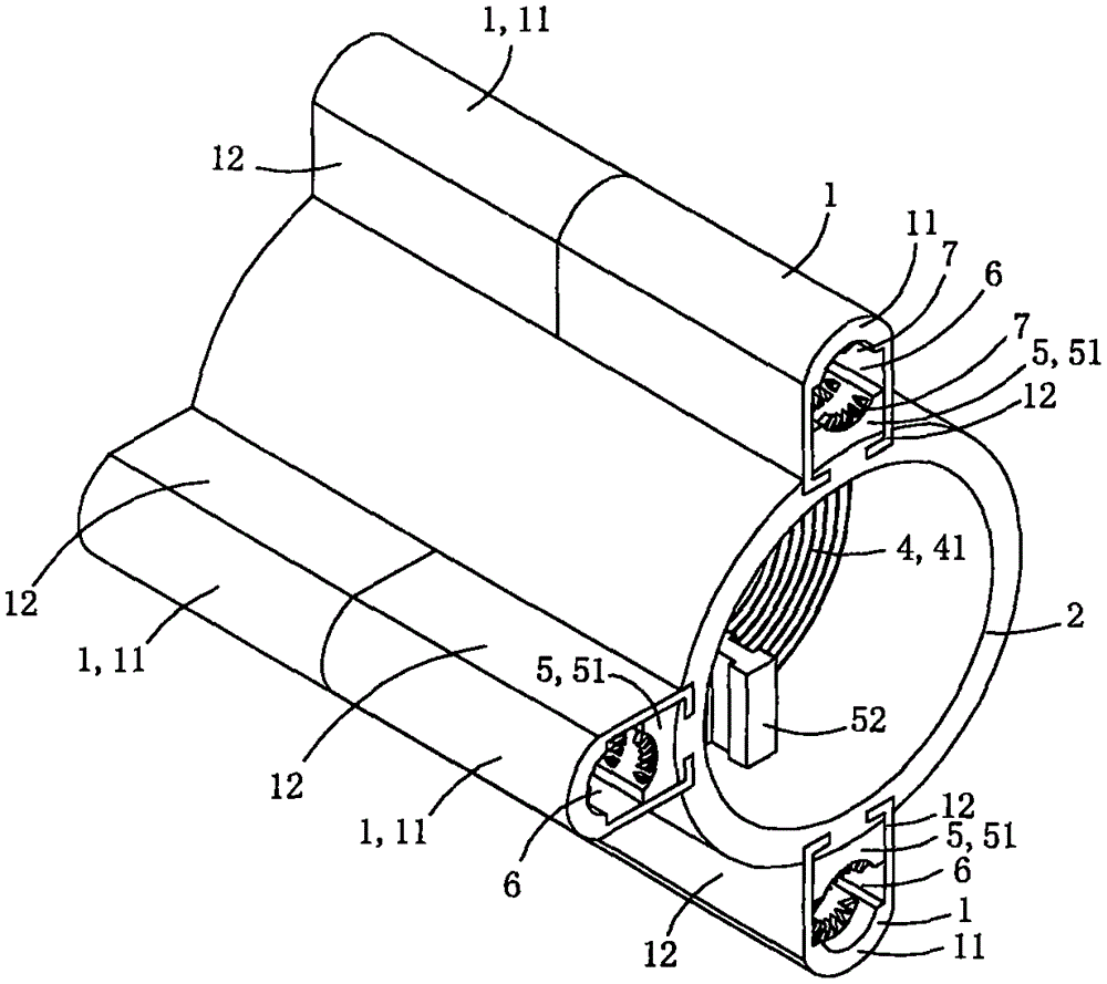
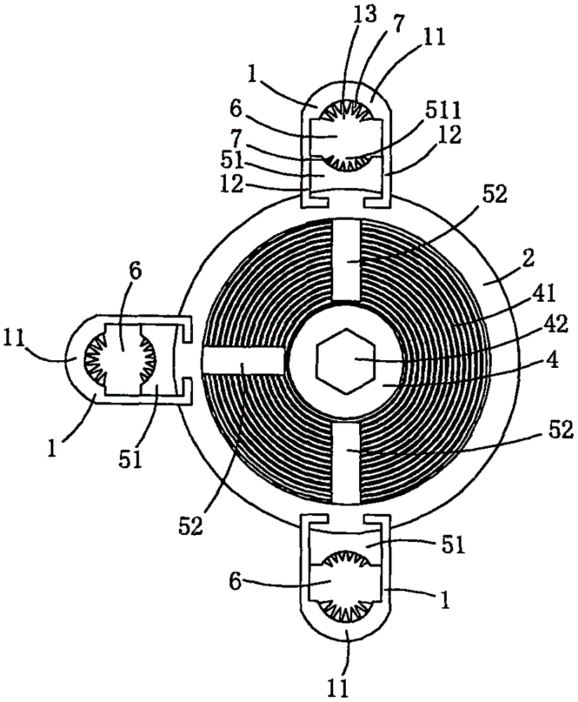
[0015] This embodiment is a kind of power connection fittings for overhead lines, see Figure 1 to Figure 4 As shown, it includes a core tube 2, two sets of pressing jaw assemblies 3, two flat nuts 4 and two sets of crimping assemblies.

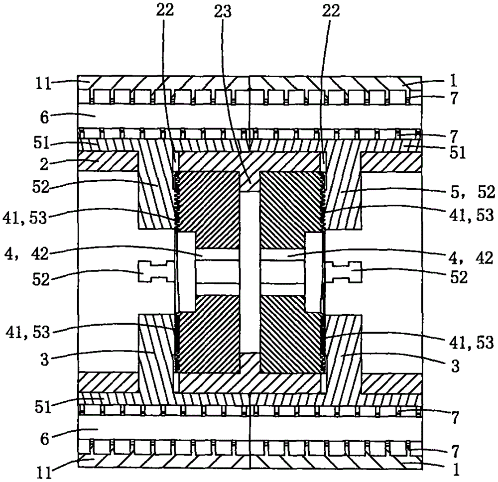
[0016] The tube wall of the core tube is provided with six radial limiting sliding holes 22, and each radial limiting sliding hole runs through the core tube tube wall along the radial direction of the core tube; each radial limiting sliding hole is located in the axial direction of the core tube. In the middle part of the top, the radial cross-sectional shape of each radial limiting hole is I-shaped; the inner peripheral wall of the core tube is provided with an annular stopper 23 protruding inward. In this embodiment, the six radial limiting holes are divided into two groups, and the three radial limiting holes in each group are used for matching with a corresponding set of pressing jaw assemblies.

[0017] Each set of crimping components ...

Embodiment 2

[0031] This embodiment is basically the same as Embodiment 1, the difference is: see Figure 5 to Figure 7 As shown, in this embodiment, a current transformer 8 is sleeved and fixed on the outer peripheral wall of each crimping piece; the current transformer 8 includes an annular base 81 and an intelligent control module 82, and the intelligent control module may include a wireless transceiver unit. When there is a leakage current in the three power cables, the ring base will induce a secondary current, and the intelligent control module will transmit the secondary current information to the remote host through the wireless transceiver unit; the intelligent control module is set on the inner wall of the ring base and the outer wall of the core tube. In the area enclosed by the outer wall of the crimping part, the space is fully utilized, which is beneficial to the overall small size and integration.

[0032] This embodiment as a whole can be used as a high-voltage zero-sequenc...


PUM


Abstract

The invention discloses an electric power connection fitting for overhead line. The electric power connection fitting for the overhead line comprises a base tube, a core tube, two sets of press claw components and two flat nuts, wherein crimping bosses are arranged on the inner circumference wall of the base tube; radial limiting slide holes are formed in the tube wall of the core tube; a stopping table is arranged on the inner circumference wall of the core tube; each set of press claw components comprise a plurality of press claws; the two flat nuts are rotationally arranged in a tube cavity of the core tube, and are separately located at two sides of the stopping table; each flat nut comprises a fastening part and a plane thread part which is matched with the press claws in one corresponding set of press claw components; and each flat nut drives the corresponding plane thread part thereof to rotate in a reciprocating manner, so that the press claws in one corresponding set of press claw components are driven to be close to or far away from the center of the core tube. The electric power connection fitting for the overhead line has an excellent anti-looseness effect.

Description

technical field [0001] The invention belongs to the technical field of power fittings for overhead lines, and in particular relates to a power connecting fitting for overhead lines. Background technique [0002] In the construction of overhead power lines, when the cables need to be branched or connected, it is necessary to use power line connecting fittings to connect two insulated conductors together. Power line connection fittings have the characteristics of easy installation, low cost, safety, reliability and maintenance-free. Cable branches can be made without cutting off the main cable or stripping the insulation layer of the cable. The joints are completely insulated and can be used for live work, and can be branched at any position on the cable; no terminal box or junction box is needed; and the joints are resistant to twisting, Shockproof, waterproof, anti-corrosion and aging; using insulated power line connection fittings as cable branches, the comprehensive benef...

Claims


Application Information

Patent Timeline
IPC IPC(8): H02G7/00
CPCH02G7/00
Inventor 胡妍
Owner 胡妍
Why Eureka
Try Eureka