Connecting hardware for power transmission and distribution

A technology for connecting fittings, power transmission and distribution, applied in conductive connection, electrical component connection, needle tip/slotted plate contact used for penetrating insulated wire/cable core wire, etc., can solve problems such as poor firmness and easy loosening , to achieve the effect of preventing retrogression, ensuring stable reliability, and excellent anti-loosening effect

Inactive Publication Date: 2017-08-18
胡妍
View PDF2 Cites 0 Cited by
  • Summary
  • Abstract
  • Description
  • Claims
  • Application Information

AI Technical Summary

Problems solved by technology

However, traditional hardware also has shortcomings. The pressure of clamping wire depends on the pressure of ordinary bolt components, which is poor in firmness and easy to loosen.

Method used


Image

  • Connecting hardware for power transmission and distribution
  • Connecting hardware for power transmission and distribution
  • Connecting hardware for power transmission and distribution

Examples


Embodiment 1)

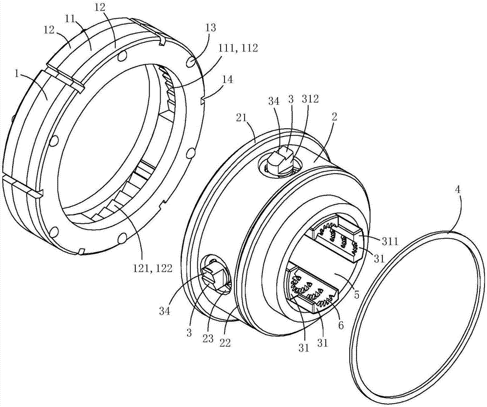
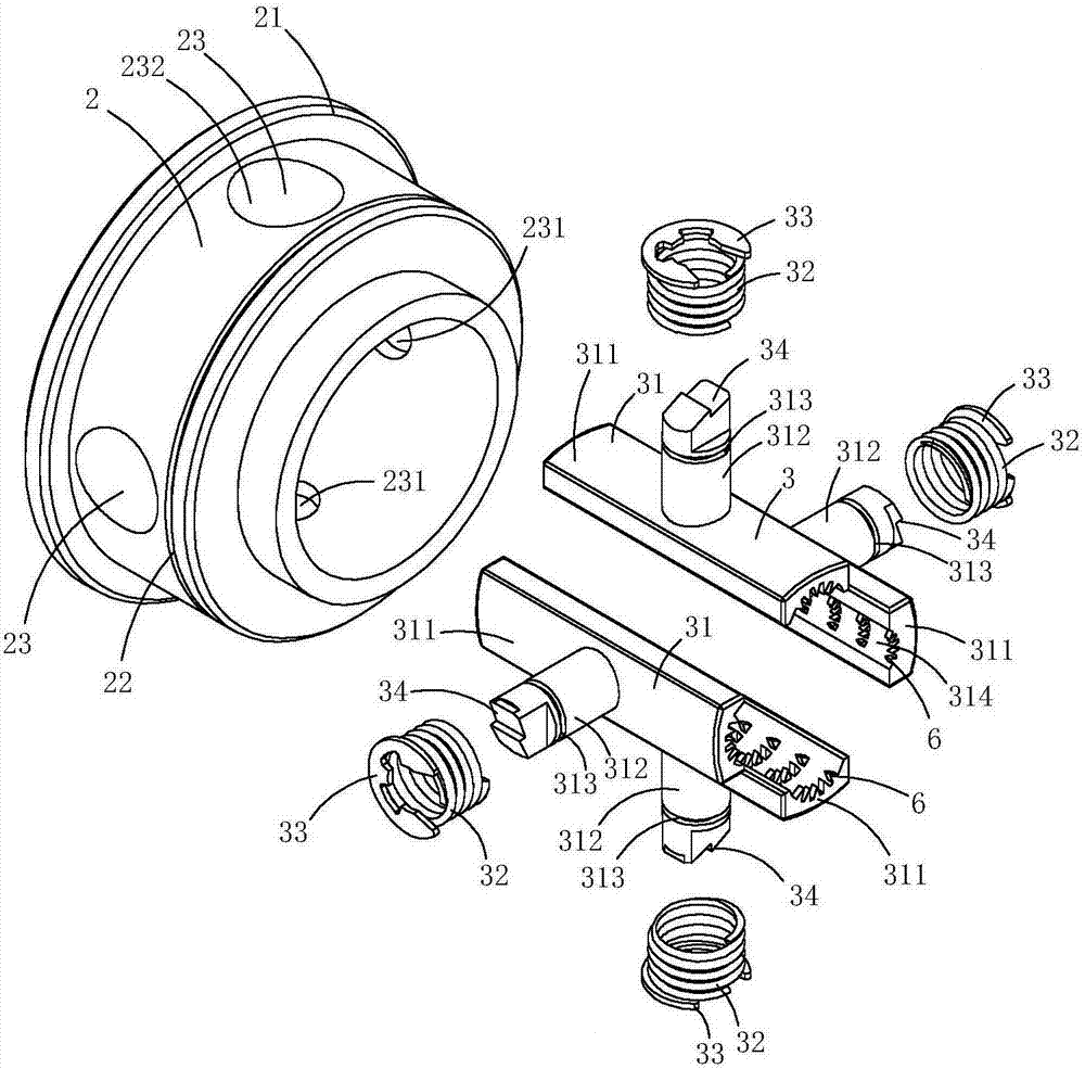
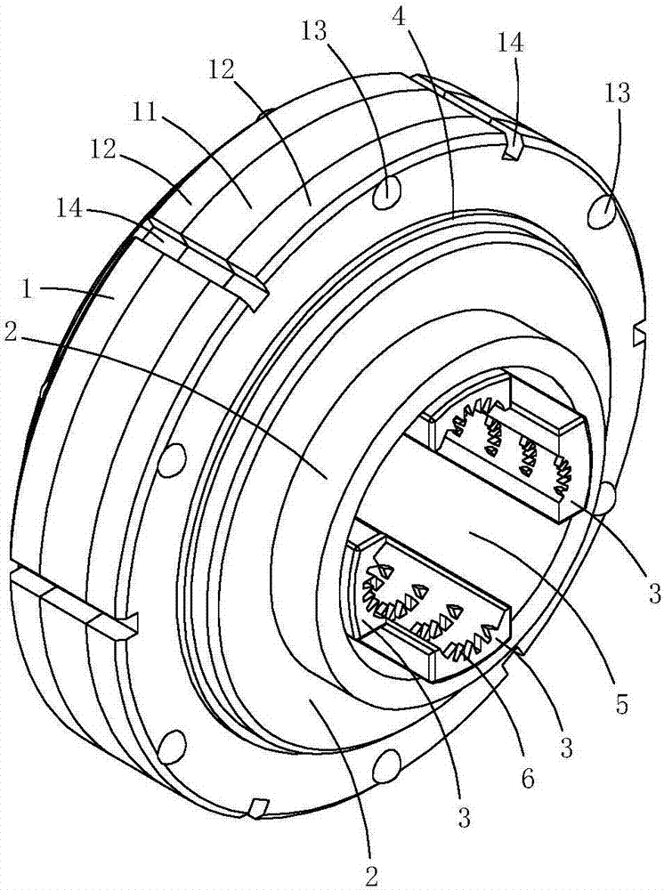
[0021] This embodiment is a kind of electric power fittings, see Figure 1 to Figure 5 As shown, it includes a pressure ring 1 , a core tube 2 , four pressure jaw assemblies 3 and an axial retaining ring 4 .

[0022] The pressure ring 1 includes a ratchet ring 11, two clamping rings 12 on both sides of the ratchet ring and a plurality of coupling rivets 13, the two clamping rings clamp the ratchet ring, and the coupling rivets penetrate through the ratchet ring and the ratchet ring along the core tube axial direction. Two clamping rings, so that the ratchet ring and the two clamping rings are fixedly connected as a whole. The inner peripheral wall of the ratchet ring is provided with a plurality of slope grooves 111, and each slope groove is provided with a plurality of wedge-shaped anti-off teeth 112; in this embodiment, the inner peripheral wall of the ratchet ring and the inner peripheral wall of the clamping ring are coplanar, The outer peripheral wall of the clamping rin...

Embodiment 2)

[0032] This embodiment is basically the same as Embodiment 1, the difference is: see Figure 6 to Figure 10 As shown, this embodiment also includes a mandrel 7 located in the lumen of the core tube; a plurality of arc-shaped clamping grooves 71 are provided on the outer peripheral wall of the mandrel, and each arc-shaped clamping groove extends axially along the core tube, and each arc-shaped clamping groove The clamping grooves are arranged opposite to the arc-shaped grooves on the inner wall of the corresponding one of the pressure jaws; each arc-shaped clamping groove and a corresponding arc-shaped groove are clamped to form a clamping hole 5; so this embodiment can form four clamping holes, which can be used for Clamp four cables at the same time.

[0033] The outer peripheral wall of the mandrel is provided with four supporting positioning convex plates 72 protruding along the radial direction of the core tube, and the inner peripheral wall of the core tube is provided wi...

Embodiment 3)

[0035] This embodiment is basically the same as Embodiment 2, the difference is: see Figure 11 As shown, this embodiment also includes a voltage transformer 8; the voltage transformer includes an annular base 81 for inductively generating a secondary voltage and an annular ring body 82 sheathed on the annular base. A clamping ring is provided with an annular installation notch 121 at one end adjacent to the ratchet ring; the voltage transformer is embedded in the installation notch; an intelligent central control module is provided in the annular ring body for controlling the outer wall of the voltage transformer The temperature sensor for temperature detection and the wireless sensing unit for sending information to the remote host; the secondary terminal of the voltage transformer, the temperature sensor and the wireless sensing unit are all connected to the intelligent central control module.

[0036]The sensing unit of the temperature sensor is arranged close to the outer...


PUM


Abstract

The invention discloses connection hardware for transmission and distribution. The hardware comprises a pressing ring, a core tube, and pressing claw components. The pressing ring is rotatingly arranged at the peripheral wall of the core tube and comprises a coronula whose inner peripheral wall is provided with a plurality of slope grooves. Each of the slope grooves is internally provided with multiple wedge-shaped anti-off teeth. The wall of the core tube is provided with multiple radial guide holes. Each of the pressing claw components comprises pressing claws and reset springs. Each of the pressing claws comprises a pressing plate part and a radial sliding column. The outer side end of each radial sliding column is provided with wedge-shaped teeth. The pressing plate part of each pressing claw is in the pipe cavity of the core tube, the radial sliding column of each pressing claw goes through a radial guide hole, and each of the wedge-shaped teeth presses corresponding wedge-shaped anti-off teeth. When the coronula is rotated, the wedge-shaped anti-off teeth are driven to rotate, and through pressing the radial sliding column of each pressing claw, the pressing plate part of each pressing claw is driven to move to the center of the core tube. The connection hardware has good electrical performance.

Description

technical field [0001] The technical field of electric power fittings for overhead lines of the present invention particularly relates to a connecting fitting for power transmission and distribution. Background technique [0002] In the construction of overhead power lines, when the cables need to be branched or spliced, it is necessary to use fittings to connect two insulated conductors together. Fittings have the characteristics of easy installation, low cost, safety, reliability and maintenance-free. Cable branches can be made without cutting off the main cable or stripping the insulation layer of the cable. The joints are completely insulated and can be used for live work, and can be branched at any position on the cable; no terminal box or junction box is needed; and the joints are resistant to twisting, Shockproof, waterproof, anti-corrosion and aging; using insulating fittings as cable branches, the comprehensive benefits are obvious, and the cost performance is bett...

Claims


Application Information

Patent Timeline
IPC IPC(8): H01R11/09H01R11/01H01R4/24H01R4/50H01F38/26H01F27/06
CPCH01F27/06H01F38/26H01R4/2412H01R4/5083H01R11/01H01R11/09
Inventor 林海涛罗永利曹春诚王杰邴龙朱家炜王鹏浩史子瑞
Owner 胡妍
Why Eureka
Try Eureka