
Full-automatic U-shaped ultrasonic top stop machine and feeding device thereof

A feeding device and ultrasonic technology, applied in the field of automatic U-shaped ultrasonic top stop machine, can solve the problems of low work efficiency, further improvement of welding effect and precision, complex wire feeding structure of the whole machine, etc., and improve the efficiency of forming and welding Effect

Active Publication Date: 2017-05-31
广州市振宇拉链机械有限公司
View PDF4 Cites 2 Cited by
  • Summary
  • Abstract
  • Description
  • Claims
  • Application Information

AI Technical Summary

Problems solved by technology

[0002] The existing full-automatic nylon zipper ultrasonic welding U-shaped double top stop machine forms the plastic flat wire into the top stop grain in the same way as the bottom stop grain of the traditional bottom stop machine. The whole machine, especially th

Method used


Image

  • Full-automatic U-shaped ultrasonic top stop machine and feeding device thereof
  • Full-automatic U-shaped ultrasonic top stop machine and feeding device thereof
  • Full-automatic U-shaped ultrasonic top stop machine and feeding device thereof

Examples


Embodiment Construction

[0032] The specific embodiment of the present invention will be further described below in conjunction with accompanying drawing:

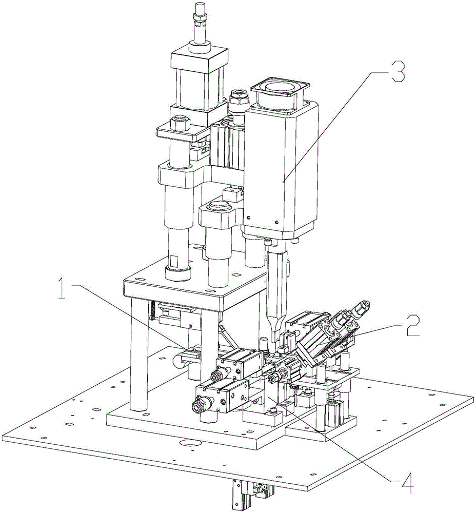
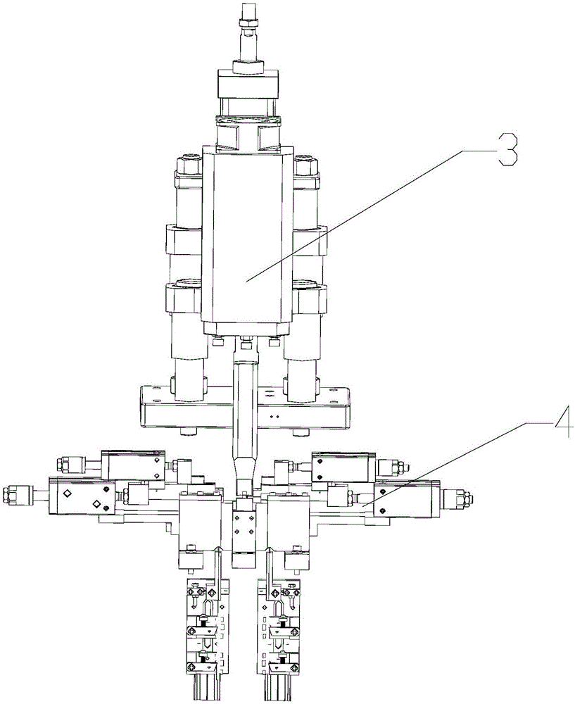
[0033] Such as Figure 1-Figure 12 As shown, the fully automatic U-shaped ultrasonic upper stop machine includes chain passing part 1, chain splitting part 2, sound wave part 3 and wire feeding part 4. The zipper is separated, and at the same time, the plastic flat wire enters from the wire feeding part 4 and is cut off to form a U-shaped top stop, and then the U-shaped top stop is welded to the zipper under the joint action of the sound wave part 3;

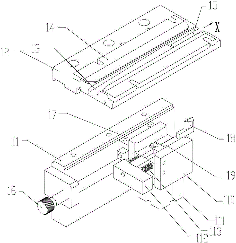
[0034]Wherein, the wire feeding part 4 includes a wire feeding mechanism and a molding die, and the wire feeding mechanism includes a pair of symmetrically arranged wire feeding bases 41, and the edge of one side of the wire feeding base 41 is evenly spaced from bottom to top. The first wire guide seat 42, the second wire guide seat 42 and the third wire guide seat 44 are installed, and the first w...


PUM


Abstract

The invention discloses a full-automatic ultrasonic welding U-shaped double-top-stop machine for nylon zippers. The machine comprises a zipper passing part and a wire conveying part; the wire conveying part comprises a wire conveying mechanism and a forming mold; the wire conveying mechanism comprises a pair of wire conveying bases which are symmetrically arranged; wire guide bases are arranged at the edge of one side of each wire conveying base; guide rails allowing flat plastic wires to pass through are arranged on the wire guide bases; and a first wire conveying and pressing rod and a second wire conveying and pressing rod are further arranged on each wire conveying base from bottom to top, wherein one end of the first wire conveying and pressing rod and one end of the second wire conveying and pressing rod are movably arranged on the wire conveying base through rotating sleeves, the other end of the first wire conveying and pressing rod and the other end of the second wire conveying and pressing rod abut against the flat plastic wires in the guide rails of the first wire guide base and the second wire guide base respectively and abut against inclined surface ends of the flat plastic wires respectively, and the second wire conveying and pressing rod is connected to a wire conveying air cylinder capable of driving the second wire conveying and pressing rod to rotate upwards. According to the machine, the first wire conveying and pressing rods carry out wire conveying, the second wire conveying and pressing rods prevent the flat plastic wires from backing up, the overall structure is simple, two U-shaped top stops can be formed and welded at a time, and the efficiency can be improved.

Description

technical field [0001] The invention relates to the field of mechanical equipment, in particular to a fully automatic U-shaped ultrasonic top stop machine. Background technique [0002] The existing full-automatic nylon zipper ultrasonic welding U-shaped double top stop machine forms the plastic flat wire into the top stop grain in the same way as the bottom stop grain of the traditional bottom stop machine. The whole machine, especially the wire feeding structure quite complicated. Moreover, the existing U-shaped top-stop machine can only complete one work at a time in the process of welding up-stop, which is low in efficiency, and the welding effect and precision need to be further improved. Therefore, there is a belt to develop an ultrasonic top stop machine with a relatively simple wire feeding structure and high forming and welding efficiency. Contents of the invention [0003] The purpose of the present invention is to overcome the deficiencies of the prior art and...

Claims


Application Information

Patent Timeline
IPC IPC(8): B29C65/78B29C65/08B29C53/02B29C53/80
CPCB29C53/02B29C53/80B29C65/08B29C65/7802
Inventor 邱萍
Owner 广州市振宇拉链机械有限公司
Learn More