High-voltage transformer

A technology of high-voltage transformers and voltage transformers, which is applied in the direction of transformers, inductors, transformer/inductor coils/windings/connections, etc., which can solve problems such as restrictions on the application and promotion of high-voltage transformers, and achieve excellent anti-loosening effects and easy installation , to ensure the effect of stability and reliability

Inactive Publication Date: 2016-05-25
胡小青
View PDF4 Cites 2 Cited by
  • Summary
  • Abstract
  • Description
  • Claims
  • Application Information

AI Technical Summary

Problems solved by technology

[0004] Most of the existing high-voltage transformers are installed by means of flange installation or bonding, and the installation position generally needs to be reserved, so the application and promotion of high-voltage transformers are more restricted

Method used


Image

  • High-voltage transformer
  • High-voltage transformer
  • High-voltage transformer

Examples


Embodiment 1

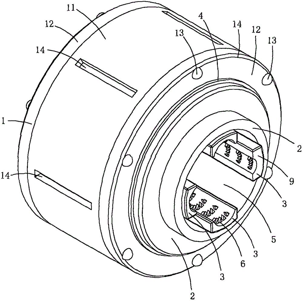
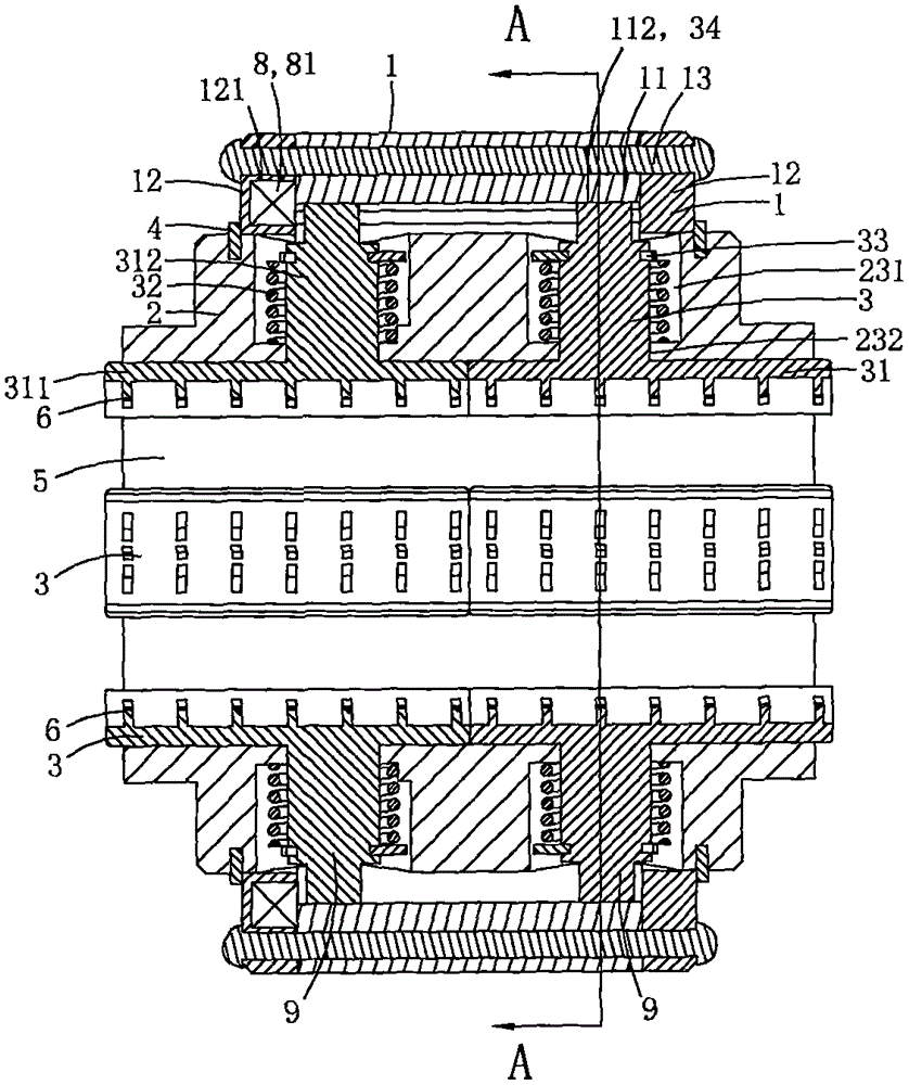
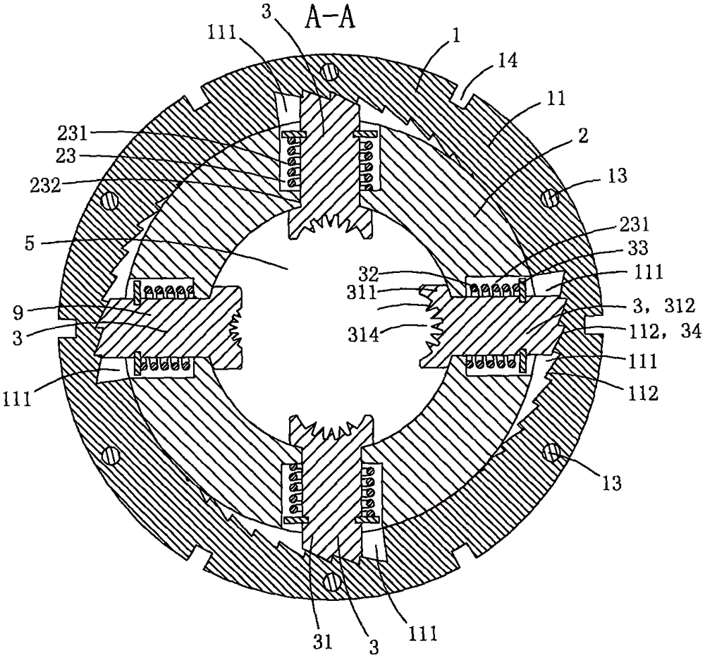
[0019] This embodiment is a high voltage transformer, see Figure 1 to Figure 5 As shown, it includes a compression ring 1 , a core tube 2 , a voltage transformer 8 , two axial retaining rings 4 and two sets of clamping assemblies 9 .

[0020] The pressure ring 1 includes a ratchet ring 11, two clamping rings 12 on both sides of the ratchet ring and a plurality of coupling rivets 13, the two clamping rings clamp the ratchet ring, and the coupling rivets penetrate through the ratchet ring and the ratchet ring along the core tube axial direction. Two clamping rings, so that the ratchet ring and the two clamping rings are fixedly connected as a whole. The inner peripheral wall of the ratchet ring is provided with a plurality of slope grooves 111, and each slope groove is provided with a plurality of wedge-shaped anti-off teeth 112; in this embodiment, the inner peripheral wall of the ratchet ring and the inner peripheral wall of the clamping ring are coplanar, The peripheral wal...

Embodiment 2

[0033] This embodiment is basically the same as Embodiment 1, the difference is: see Figure 6 and Figure 7 As shown, the voltage transformer 8 in this embodiment also includes an intelligent control module 82; the outer peripheral wall of the core tube is provided with a placement groove 25, and the intelligent control module is arranged in the placement groove; the intelligent control module may include a wireless transceiver unit and an alarm The buzzer and the intelligent control module transmit the secondary voltage or current signal sensed by the ring base to the remote host through the wireless transceiver unit, so as to realize precise remote unmanned monitoring; this structure can make full use of the space and is conducive to the overall small size and integration.

Embodiment 3

[0035] This embodiment is basically the same as Embodiment 2, the difference is: see Figure 8 As shown, in this embodiment, the annular base body of the voltage transformer is no longer arranged in the clamping ring. In this embodiment, the annular base body of the voltage transformer is fixedly arranged on the outer peripheral wall of the core tube. This scheme is also feasible, and the structure is more Compact and easy to manufacture and process.


PUM


Abstract

The invention discloses a high-voltage transformer, which comprises a compression ring, a core tube, a current transformer body and two sets of wire clamping components, wherein the compression ring is rotationally arranged on the outer circumference wall of the core tube; the compression ring comprises a ratchet ring of which the inner circumference wall is provided with a plurality of slope grooves; a plurality of wedge-shaped anti-drop teeth are arranged in the slope grooves; a plurality of radial guide holes are formed in the tube wall of the core tube; each wire clamping component comprises a plurality of press claw components which are evenly distributed along the circumferential direction of the core tube; each press claw component comprise a plurality of press claws and reset springs for providing reset elasticity to the press claws; each press claw comprises a press plate part and a radial slide column; wedge-shaped teeth are arranged on the radial slide columns; the press plate parts of the press claws are located in a tube cavity of the core tube; each radial slide column passes through one radial guide hole; each wedge-shaped tooth is propped against corresponding one wedge-shaped anti-drop tooth; the current transformer body comprises an annular base body; the ratchet ring synchronously drives the press plate parts in the two sets of wire clamping components to move towards the center of the core tube when rotating. The high-voltage transformer is relatively stable to install.

Description

technical field [0001] The invention belongs to the technical field of high-voltage electric power, and in particular relates to a high-voltage transformer. Background technique [0002] High-voltage transformers are transformers suitable for converting large voltages into small voltages or converting large currents into small currents in 1kv to 220kv power systems for easy measurement, protection, and use. [0003] Most of the existing high-voltage transformers are electromagnetic induction transformers, the working principle is the same as that of the transformer, and the basic structure is also the iron core and the primary and secondary windings. The main functions of high voltage transformers are as follows: convert high voltage into low voltage, convert large current into small current, and then use it for measurement, control and protection. This can not only increase the range of measuring instruments, facilitate the standardization of instruments, reduce the voltag...

Claims


Application Information

Patent Timeline
Patent Type & Authority Applications(China)
IPC IPC(8): H01F27/06H01F38/26H01F27/28H01R4/24
CPCH01F27/06H01F27/28H01F38/26H01R4/2404H01R2201/22
Inventor 胡小青
Owner 胡小青
Why Eureka
Try Eureka