Unlock instant, AI-driven research and patent intelligence for your innovation.

Control circuit

A control circuit and control unit technology, applied in emergency protection circuit devices, electrical components, motor generators/starters, etc., can solve the problem of burnout, large reverse voltage of control IC, increase of control circuit layout area and production cost, etc. question

Inactive Publication Date: 2018-06-26
ADDA
View PDF3 Cites 0 Cited by
  • Summary
  • Abstract
  • Description
  • Claims
  • Application Information

AI Technical Summary

Problems solved by technology

Since the general control IC uses direct current as its working voltage, the power supply must supply positive voltage to make the control IC operate normally. Therefore, if the power supply is reversed due to installation errors, the control IC will Burned due to excessive reverse voltage
In addition, when the electronic device is a motor, if the motor is to have forward rotation and reverse rotation direction at the same time, a steering control circuit or a steering control IC must be provided to achieve this, which increases the layout of the control circuit. area and production cost

Method used


Image

  • Control circuit
  • Control circuit
  • Control circuit

Examples


no. 1 example

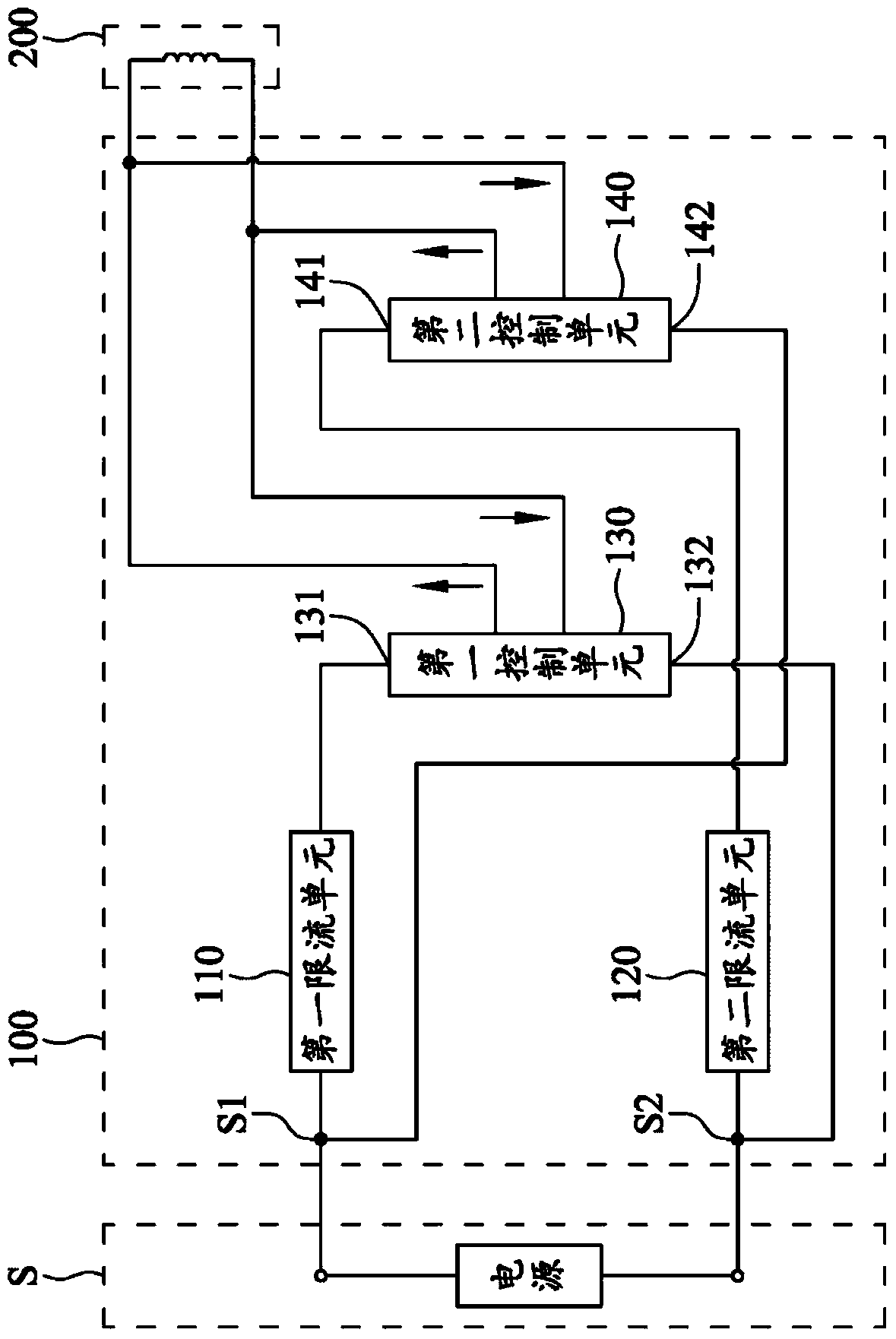
[0051] see figure 1 , is the first embodiment of the present invention, a circuit block diagram of a control circuit 100, the control circuit 100 includes a first power supply terminal S1, a second power supply terminal S2, a first current limiting unit 110, and a second current limiting unit 120 , the first control unit 130 and the second control unit 140, the first power terminal S1 and the second power terminal S2 are electrically connected to the power supply S to receive the voltage supplied by the power supply S, and the first control unit 130 and the The second control unit 140 is used to respectively output the first control signal and the second control signal to the electronic device 200 to drive the electronic device 200 to act.

[0052] see figure 1 One end of the first current limiting unit 110 is electrically connected to the first power supply terminal S1, one end of the second current limiting unit 120 is electrically connected to the second power supply ter...


PUM


Abstract

The invention relates to a control circuit. A power supply voltage is received to output a control signal to drive electronic equipment, wherein the control circuit comprises a first current limiting unit, a second current limiting unit, a first control unit and a second control unit; when the first current limiting unit permits a current to flow into the first control unit to start the first control unit, the second current limiting unit prevents the current from flowing into the second control unit; and when the second current limiting unit permits the current to flow into the second control unit to start the second control unit, the first current limiting unit prevents the current from flowing into the first control unit, so that, no matter that the voltage supplied to the control circuit by a power supply is positive or negative, the first control unit or the second control unit can output the control signal, and the electronic equipment normally runs.

Description

technical field [0001] The present invention relates to a control circuit, in particular to a control circuit with a first control unit and a second control unit. Background technique [0002] see Figure 9 , a schematic diagram of a control circuit of a known electronic device, which has a power supply, a control IC and an electronic device. The power supply is used to provide an operating voltage to the control IC to start the control IC. After the control IC is started, it outputs a control signal to the control IC. electronic equipment to drive and control the electronic equipment. Since the general control IC uses direct current as its working voltage, the power supply must supply positive voltage to make the control IC operate normally. Therefore, if the power supply is reversed due to installation errors, the control IC will Burned due to excessive reverse voltage. In addition, when the electronic device is a motor, if the motor is to have forward rotation and rever...

Claims


Application Information

Patent Timeline
Patent Type & Authority Patents(China)
IPC IPC(8): H02P1/22H02H7/085
Inventor 庄钰维陈雪真
Owner ADDA