Heat-dissipation device

A technology of heat sinks and heat sinks, applied in the direction of cooling/ventilation/heating transformation

Active Publication Date: 2016-06-01
ASIA VITAL COMPONENTS SHENZHEN CO LTD
View PDF9 Cites 2 Cited by
  • Summary
  • Abstract
  • Description
  • Claims
  • Application Information

AI Technical Summary

Problems solved by technology

[0010] The secondary purpose of the present invention is to provide a heat dissipation device that improves the deformation of the heat conducting element

Method used


Image

  • Heat-dissipation device
  • Heat-dissipation device
  • Heat-dissipation device

Examples


Embodiment Construction

[0049] The above-mentioned purpose of the present invention and its structural and functional characteristics will be described based on the preferred embodiments of the accompanying drawings.

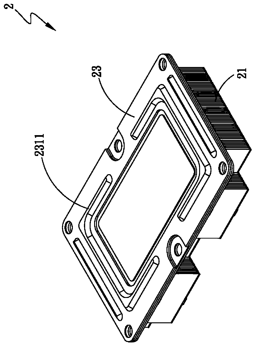
[0050] Such as Figure 1A and 1B And 2A and 2B are the perspective view of the support member of the first embodiment of the heat dissipation device of the present invention and the three-dimensional exploded view and three-dimensional combination view of the heat dissipation device. As shown in the figure, a heat dissipation device 2 includes a heat dissipation member 21 and a heat conduction Part 22 and a supporting part 23, the cooling part 21 has several cooling fins 211 and forms at least one depression 212;

[0051] One side of the heat conduction element 22 is attached to the heat dissipation element 21 correspondingly, and at least one joint portion 224 and at least one through hole 225 are formed on opposite sides of the heat conduction element 22 ;

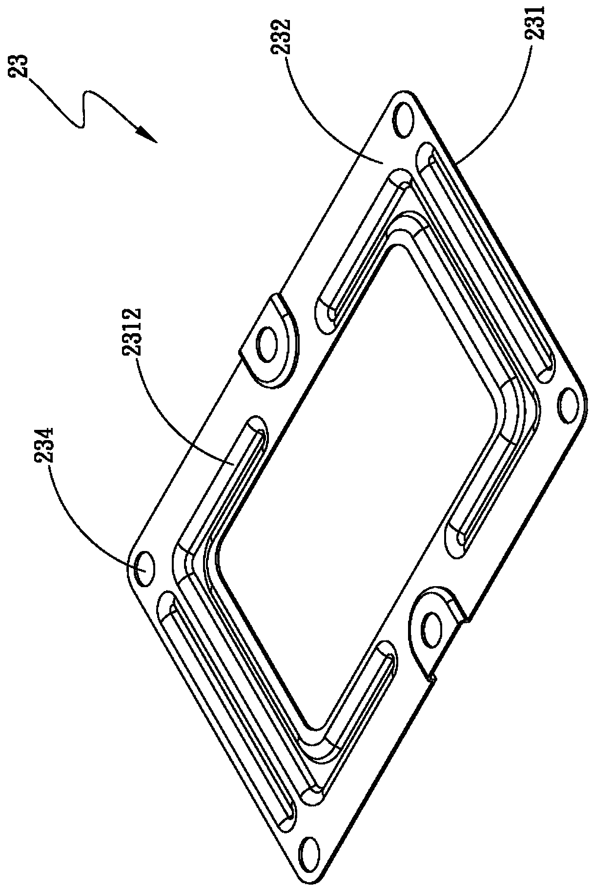
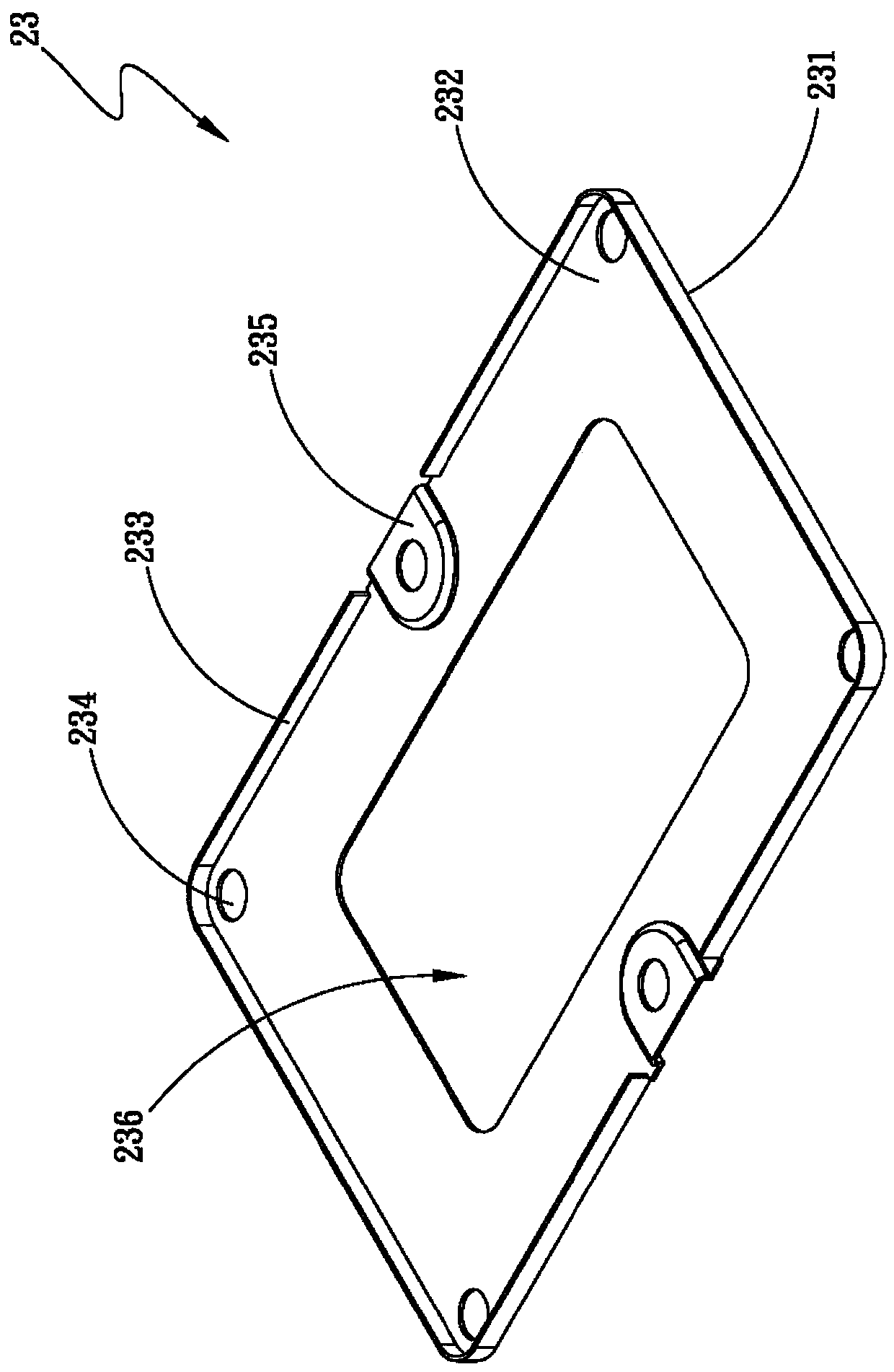
[0052] The supporting me...


PUM


Abstract

The invention discloses a heat-dissipation device, and the device comprises a heat dissipation part, a heat conduction part, and a supporting part. One side of the heat conduction part is correspondingly attached to the heat dissipation part, and the opposite peripheral sides of the heat conduction part respectively form at least one assembly connection part and a perforation, and the supporting part is correspondingly assembled at the other side of the heat conduction part. The opposite peripheral sides of the supporting part also respectively form at least one butting joint part, wherein the butting joint part is combined with the assembly connection part. Moreover, a hollow-out region is formed at the central position of the supporting part. Through the above design, the device can greatly increases a withstood locking force when the heat conduction part and the heat dissipation part are combined, and improves the deformation of the heat conduction part.

Description

【Technical field】 [0001] The invention relates to a heat dissipation device which can not only greatly increase the locking force when combined with the heat dissipation element, but also improve the deformation of the heat conduction element. 【Background technique】 [0002] Due to the advancement of the technology era, the operating performance of electronic components is getting higher and higher, so that the functional requirements for the heat dissipation unit are also increasing. In order to increase the heat dissipation effect, the conventional heat dissipation units have adopted a large number of stacked heat dissipation fins. , and continue to develop and improve the heat dissipation fins, so high-efficiency heat dissipation devices have become one of the most important research and development priorities in the industry today, or a heat dissipation element is arranged above the electronic component and through the heat dissipation element. The element dissipates hea...

Claims


Application Information

Patent Timeline
IPC IPC(8): H05K7/20
Inventor 林源忆
Owner ASIA VITAL COMPONENTS SHENZHEN CO LTD
Why Eureka
Try Eureka