Reinforced fixing support apparatus
A fixed support and plane technology, applied in the direction of support structure installation, electrical components, casing/cabinet/drawer components, etc., can solve problems such as difficulties, inconvenient use, increased fixed equipment parts and costs, etc.
- Summary
- Abstract
- Description
- Claims
- Application Information
AI Technical Summary
Problems solved by technology
Method used
Image

Examples
Embodiment 1
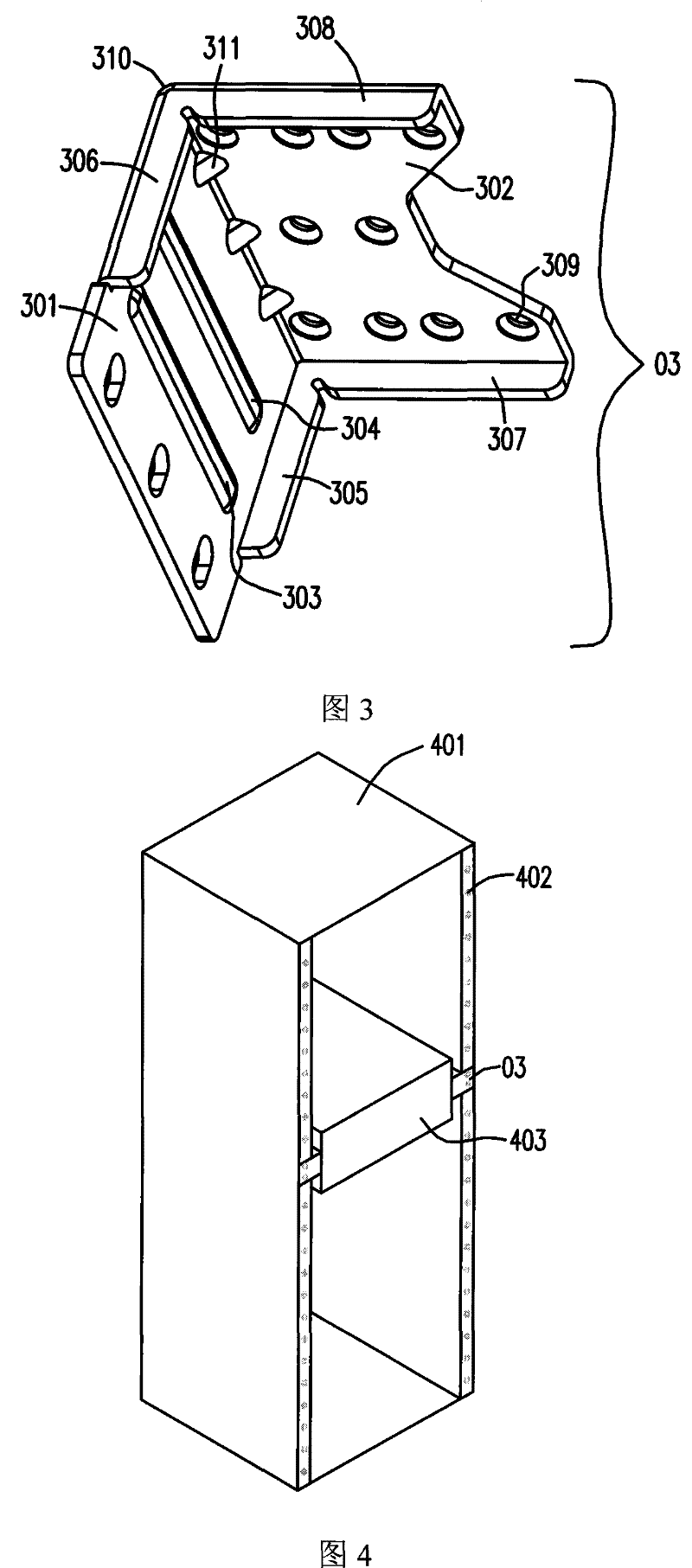
[0033] Such as figure 2 Shown is a schematic structural view of the reinforced fixed support bracket in Embodiment 1 of the present invention. The reinforced fixed support bracket 02 includes a first plane body 201 , a second plane body 202 , rectangular protrusions 203 and 204 , first folds 205 and 206 , and a bent corner 208 . At the same time, the first plane body 201 and the second plane body 202 each have a plurality of holes 209, which are used as connections with the equipment to be fixed and the cabinet (not shown in this figure).
[0034] With the above-mentioned bracket, when the equipment to be fixed is heavy, the suspended surface (ie, the first plane body 201 in this embodiment) is prone to distortion and deformation. In order to strengthen the support of the suspended surface, a first flap 205 and 206 are respectively arranged on the upper and lower sides of the first plane body 201, wherein the first flaps 205 and 206 are respectively perpendicular to the firs...
Embodiment 2
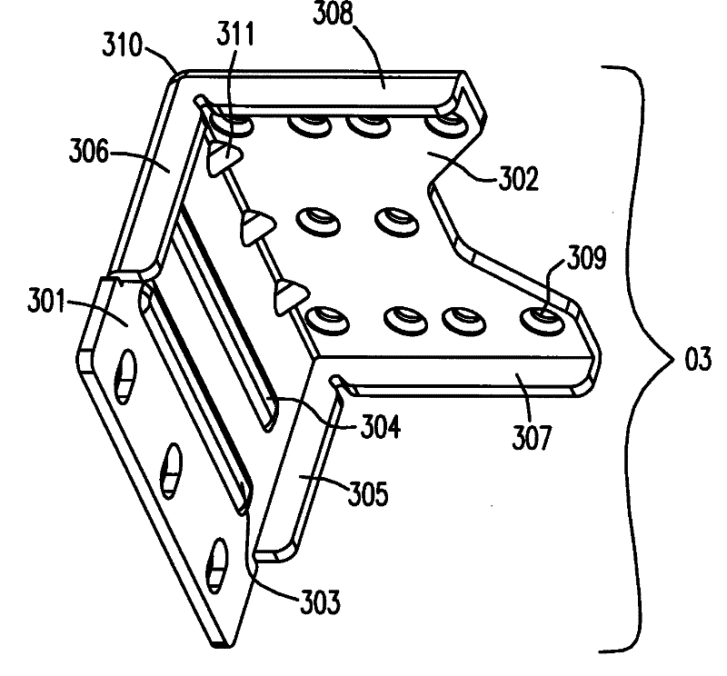
[0036] image 3 Shown is a schematic diagram of the reinforced fixing support device in the second embodiment of the present invention. The difference from Embodiment 1 is that the reinforced fixing support device 03 in this embodiment includes a first flat surface 301, a second flat surface 302, rectangular raised strips 303 and 304, and a first flap with the same structure as that of Embodiment 1. 305 and 306 , and a bend angle 310 formed by the connection of the first plane 301 and the second plane 302 , and a plurality of holes 309 also include a second fold 307 and 308 and a protruding structure 311 .
[0037] In this embodiment, not only a reflex structure is formed on both sides of the first plane 301, but also a reflex structure is formed on both sides of the second plane 302, that is, the second folds 307 and 308 are respectively perpendicular to the second Plane 302. Wherein, the first flaps 305 and 306 , the second flaps 307 and 308 are integrally formed with the ...
PUM
 Abstract
Description
Claims
Application Information
 - R&D
- Intellectual Property
- Life Sciences
- Materials
- Tech Scout
- Unparalleled Data Quality
- Higher Quality Content
- 60% Fewer Hallucinations
Browse by: Latest US Patents, China's latest patents, Technical Efficacy Thesaurus, Application Domain, Technology Topic, Popular Technical Reports.
© 2025 PatSnap. All rights reserved.Legal|Privacy policy|Modern Slavery Act Transparency Statement|Sitemap|About US| Contact US: help@patsnap.com