
Support roller mounted in a floating manner

A technology for supporting rollers and supporting parts, which is applied to furniture parts, household utensils, drawers, etc., and can solve problems such as deformation of rolling elements

Active Publication Date: 2016-06-01
JULIUS BLUM GMBH
View PDF9 Cites 0 Cited by
  • Summary
  • Abstract
  • Description
  • Claims
  • Application Information

AI Technical Summary

Problems solved by technology

However, the following problems can arise in conventional drawer extensions: the rolling elements are loaded by permanently acting forces (for example the weight of a filled drawer) and thus deformable

Method used


Image

  • Support roller mounted in a floating manner
  • Support roller mounted in a floating manner
  • Support roller mounted in a floating manner

Examples


Embodiment Construction

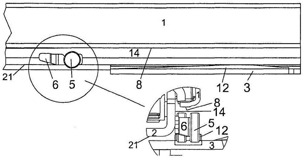
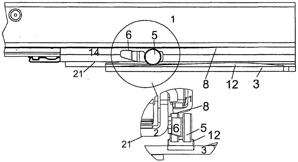
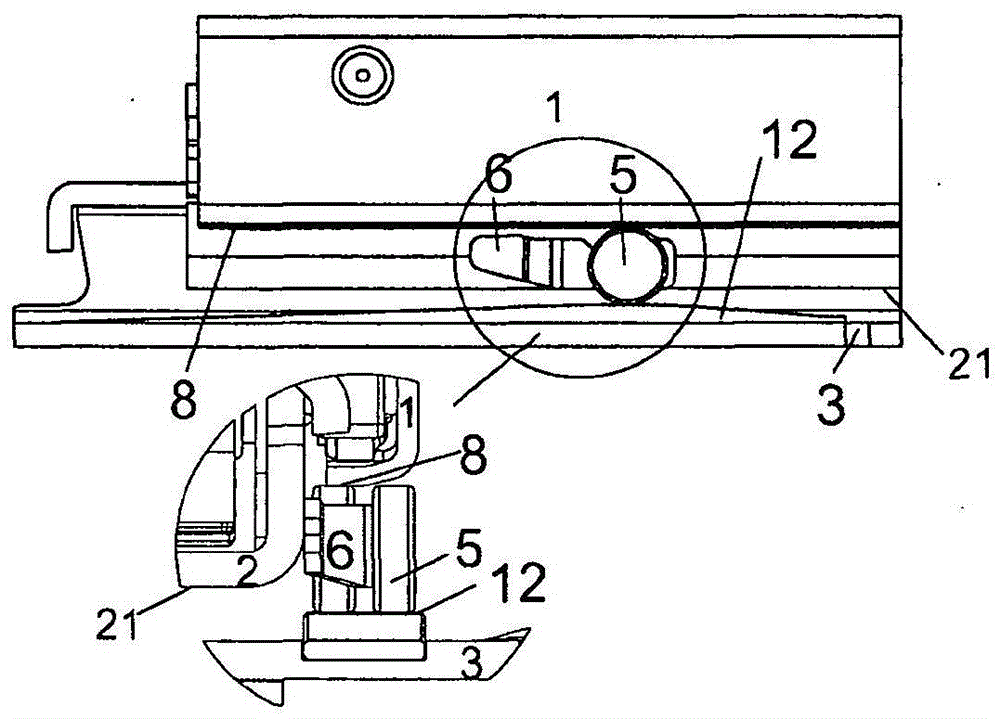
[0023] Figure 1a The drawer extension 10 is shown in the extended state. In the upper region, the drawer rail 1 , the side webs 14 located below it, which belong to the central rail 2 , and the ramp 12 on the body rail 3 can be seen. The support rollers 5 rest on a support 6 which is fixedly connected to the lateral webs 14 belonging to the central rail 2 . In the detail view visible below it, see support roller 5 or in the upper side view, it can be seen that support roller 5 is located in the region in front of ramp 12 and thus remains loose in its recess 19 . There is therefore no interaction between the ramp 12 , the support roller 5 and the running surface 8 on the drawer rail 1 . The individual rails thus slide on their rolling bodies 7 and 9 and the support rollers 5 remain unloaded.

[0024] Figure 1b It shows how, during the closing process of the drawer extension 10 , the support roller 5 now moves upwards in its recess 19 on the uphill region of the ramp 12 an...


PUM


Abstract

The invention relates to a drawer pull-out device (10) comprising a body rail with a securing section for securing to a furniture body, a drawer rail (1) which is to be secured to a drawer (11) and which is movably mounted relative to the body rail (3), and a central rail (2) which is movably mounted between the body rail (3) and the drawer rail (1). The central rail has a lateral web which faces the securing section, and a bearing (6) is provided with at least one support roller (5) by means of which the drawer rail (1) can be supported on the body rail (3). The at least one support roller (5) is mounted in a vertically movable manner by means of the bearing (6), and the support roller (5) is arranged between the lateral web (14) of the central rail (2) and the securing section (15) of the body rail (3).

Description

technical field [0001] The invention relates to a drawer pull-out device, which comprises: a body rail with a fixing section for fixing on a furniture body; Bearing; middle rail, which is movably mounted between the body rail and the drawer rail, wherein the middle rail has lateral webs facing the fastening section. Background technique [0002] Drawer pull-outs of a similar type already belong to the prior art. In conventional drawer extensions, however, the problem can arise that the rolling elements are loaded by permanently acting forces (for example the weight of a filled drawer) and thus deform. In particular, the forces acting on the rolling elements in the closed state of the drawer extension are higher than those acting on the rolling elements during the drawer extension process. Contents of the invention [0003] The object of the invention is to provide a drawer extension of the type mentioned at the outset, which is designed such that the rolling elements are...

Claims


Application Information

Patent Timeline
IPC IPC(8): A47B88/10A47B88/493
CPCA47B88/40A47B88/493A47B2210/0008
Inventor W·维奥兰德
Owner JULIUS BLUM GMBH
Learn More