
Fixture device for welding pipe structures

A fixture device and pipe fitting technology, which is applied in the direction of auxiliary devices, welding equipment, auxiliary welding equipment, etc., can solve the problems of fixed and inability to freely adjust the welding angle of pipe fittings, etc.

Inactive Publication Date: 2016-06-08
CHINA MCC5 GROUP CORP
View PDF7 Cites 4 Cited by
  • Summary
  • Abstract
  • Description
  • Claims
  • Application Information

AI Technical Summary

Problems solved by technology

[0003] The purpose of the present invention is to overcome the deficiencies of the prior art and provide a fixture device for pipe fitting structure welding, which solves the problems that the pipe fittings are fixed during welding and the welding angle of the pipe fittings cannot be adjusted freely.

Method used


Image

  • Fixture device for welding pipe structures
  • Fixture device for welding pipe structures
  • Fixture device for welding pipe structures

Examples


Embodiment 1

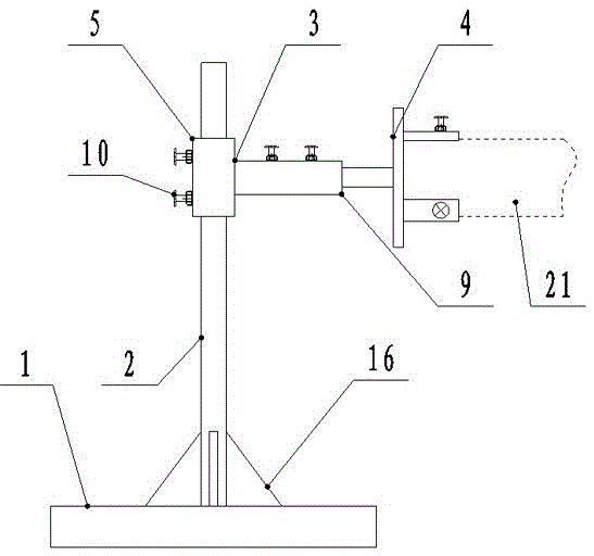
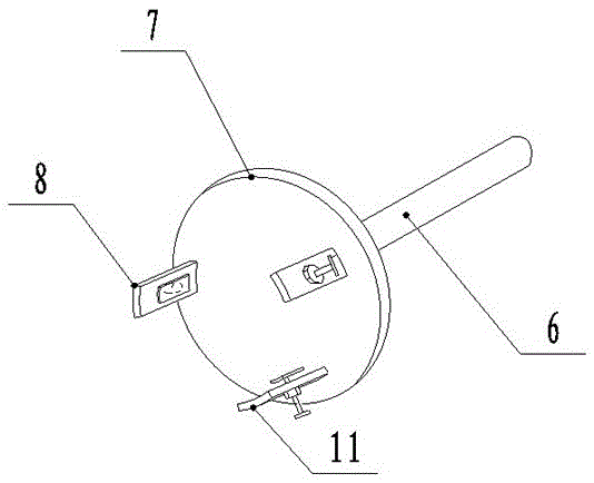
[0027] Such as Figure 1-2 As shown, a fixture device for pipe fitting structure welding according to the present invention includes a base 1, a column 2, a T-shaped joint 3 and a pipe chuck device 4, the column 2 is arranged on the base 1, and 5 sets of horizontal pipe joints of the T-shaped joint 3 It is arranged on the column 1; the connection between the column and the base 1 is provided with a reinforcing rib 16. The pipe chuck device 4 includes a shaft joint 6, a chuck 7 and jaws 8, the shaft joint 6 is arranged at the center of one disk surface of the chuck 7, and three pieces of jaws 8 are evenly distributed in a ring on the other disk surface of the chuck 7; The shaft connection 6 of the chuck device 4 is inserted into the longitudinal pipe connection 9 of the T-joint 3 .

[0028] Two sets of locking bolts 10 are arranged on the transverse pipe joint 5 of the T-shaped joint 3 . Two sets of locking bolts 10 are arranged on the longitudinal pipe joint 9 of the T-shape...

Embodiment 2

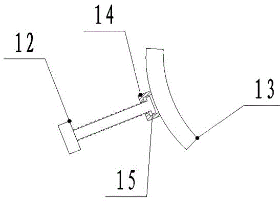
[0031] Such as image 3 As shown, the present invention is a fixture device for pipe fitting structure welding. On the basis of Embodiment 1, a buckle cap 14 is provided on the back of the clamping block 13, and a ring protrusion 15 is provided at the end of the fastening adjustment bolt 12. The fastening adjustment The end of the bolt 12 is set in the buckle cap 14 through the ring protrusion 15 , and the clamping block 13 is free to rotate around the end of the fastening adjusting bolt 12 . The clamping block 13 is arc-shaped.

Embodiment 3

[0033] Such as Figure 4 As shown, the present invention is a fixture device for pipe fitting structure welding. On the basis of Embodiment 1, the longitudinal pipe joint 9 of the T-shaped joint 3 is a bent structure. The longitudinal pipe joint 9 includes a fixed pipe joint 17 and a folded pipe joint 18, the fixed pipe joint 17 and the folded pipe joint 18 are connected by a groove interface and a raised joint, and the grooved joint and the raised joint Connected by a pin shaft 19, the groove interface and the protruding joint are positioned by a positioning bolt 20 to locate the folding angle, and the folding pipe joint 18 can be folded and rotated around the fixed pipe joint 17 through the pin shaft 19, and a positioning bolt 20 is provided on the groove interface Mounting holes are provided on the corresponding protruding joints with adjustment holes for the positioning of several positioning bolts 20. The positioning bolts 20 pass through the mounting holes and the adjust...


PUM


Abstract

The invention discloses a fixture device for welding pipe structures. The fixture device comprises a base, a stand column, a T-shaped joint and a pipe chuck device; the stand column is arranged on the base; a transverse pipe joint of the T-shaped joint coats the stand column; the pipe chuck device includes a shaft joint, a chuck and clamping jaws; the shaft joint is arranged in center of one disc surface of the chuck; three clamping jaws are annularly and uniformly distributed on the other disc surface of the chuck; and the shaft joint of the pipe chuck device is inserted in a longitudinal pipe joint of the T-shaped joint. The T-shaped joint is connected with the stand column, so that the height of the fixture can be adjusted during welding; two sets of locking bolts are arranged on the transverse pipe joint of the T-shaped joint, so that the T-shaped joint is conveniently adjusted and fixed on the stand column; and the pipe chuck device and the T-shaped joint are connected through the longitudinal pipe joint, the pipe chuck device is convenient to drive welded pipes to rotate.

Description

technical field [0001] The invention relates to the field of welding fixtures, in particular to a fixture device for pipe fitting structure welding. Background technique [0002] The pipe fitting welding fixture is a good helper in the pipe fitting welding process. The currently used pipe fitting welding fixture is mainly a bench vise, or a welding fixture that fixes a dead angle. The bench vise cannot realize the angle welding of the pipe fittings, and the bench vise is heavy, not easy to move, and easy to hurt people. The welding fixture fixed at a dead angle cannot flexibly meet the welding needs. If the angle of the welded pipe fittings is flexible and changeable, a lot of investment is required. This fixture takes up a lot of space and requires a huge investment. Contents of the invention [0003] The purpose of the present invention is to overcome the deficiencies of the prior art and provide a fixture device for pipe fitting structure welding, which solves the prob...

Claims


Application Information

Patent Timeline
Patent Type & Authority Applications(China)
IPC IPC(8): B23K37/053
CPCB23K37/0533B23K37/0538
Inventor 唐丽姜友荣余友琼刘云辉殷仕蓉
Owner CHINA MCC5 GROUP CORP
Learn More