Bar material conveying device
A technology for conveying devices and materials, applied in the direction of conveyors, conveyor objects, transportation and packaging, etc., can solve the problems of waste of equipment resources, affecting cigarette production efficiency, starting one of them, etc.
- Summary
- Abstract
- Description
- Claims
- Application Information
AI Technical Summary
Problems solved by technology
Method used
Image
Examples
Embodiment 1
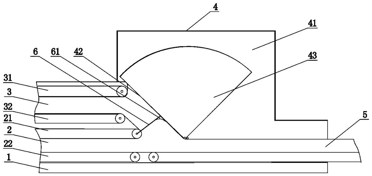
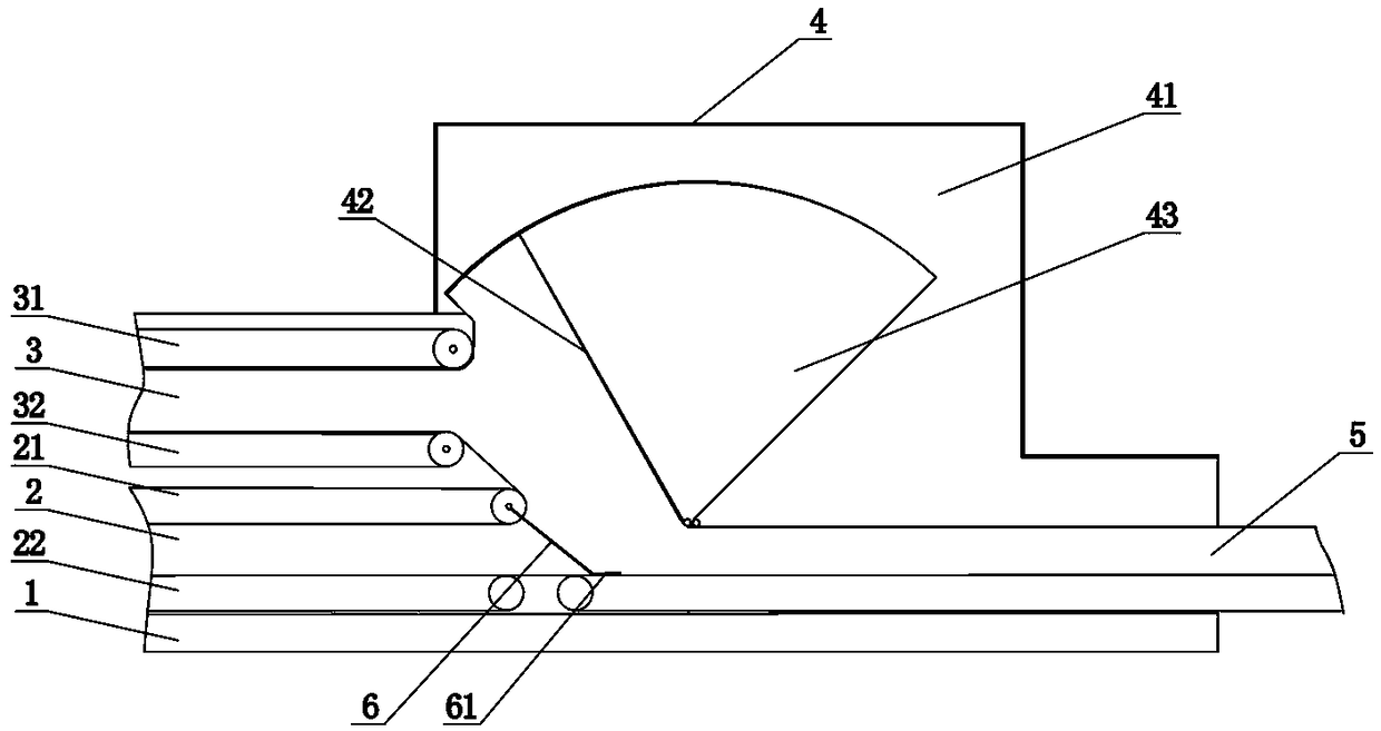
[0017] like figure 1 and figure 2 As shown, a rod-shaped material conveying device includes two groups of material input channels, a material temporary storage cavity 4 and a group of material output channels 5, wherein the two groups of material input channels are material input channel 2 and material input channel 3 respectively. , using the material input channel 2 and the material input channel 3 to realize the input of double rod-shaped material flow. A channel opening and closing conversion flap 6 is arranged between the material input channel 2 and the outlet of the material input channel 3, and the channel opening and closing conversion flap 6 can be freely rotated to utilize the difference in the conveying flow rate of rod-shaped materials in different channels. , and then realize the free switching of the material input channel 2 and the material input channel 3 . The material temporary storage cavity 4 is respectively provided with a material inlet and a material...
Embodiment 2
[0024] This embodiment is based on Embodiment 1, and provides a more specific implementation manner. The main differences are as follows: figure 1 and figure 2 As shown, the material temporary storage chamber 4 includes a casing 41 and a rotating swing arm 42 disposed in the casing 41 , the material inlet is opened on one side of the casing 41 , and the material outlet is opened at At the bottom of the casing 41, the rotating swing arm 42 is hinged at the material inlet. When the rotating swing arm 42 rotates, a material buffer space 43 is formed with the casing 41, and the material output channel 5 is arranged at the material inlet. the bottom of the casing 41.
[0025] In this embodiment, a specific material temporary storage chamber 4 is provided, and the storage space of the material temporary storage chamber 4 can be determined by the rotation angle of the rotating swing arm 42 . Since the material input channel 2 is a normally open channel, it is connected to the upst...
Embodiment 3
[0030] This embodiment is based on Embodiment 2, and provides a more specific implementation manner. The main differences are as follows: figure 1 and figure 2 As shown, the material input channel 2 and the material input channel 3 are arranged in parallel to ensure the smooth input of rod-shaped materials. The material input channel 2 is composed of an upper belt conveyor mechanism 21 and a lower belt conveyor 22. The material input channel 3 is composed of an upper belt-shaped conveying mechanism 31 and a lower belt-shaped conveyor 32; One end of the channel opening and closing conversion flap 6 is hinged at the outlet of the material input channel 2 .
[0031] Since the input speed of the rod-shaped material in the material input channel 2 and the material input channel 3 is different, the pressing force on the opening and closing conversion flap 6 of the channel is different.
[0032] like figure 1As shown in the figure, when the other end of the channel opening and cl...
PUM
 Abstract
Description
Claims
Application Information
 - R&D
- Intellectual Property
- Life Sciences
- Materials
- Tech Scout
- Unparalleled Data Quality
- Higher Quality Content
- 60% Fewer Hallucinations
Browse by: Latest US Patents, China's latest patents, Technical Efficacy Thesaurus, Application Domain, Technology Topic, Popular Technical Reports.
© 2025 PatSnap. All rights reserved.Legal|Privacy policy|Modern Slavery Act Transparency Statement|Sitemap|About US| Contact US: help@patsnap.com


