High workpiece and short workpiece separating tool

A workpiece, high and low technology, applied in the field of high and low workpiece material distribution tooling, can solve the problems of troublesome, low work efficiency, labor and so on

Inactive Publication Date: 2016-06-08
WUXI QINGYANG MACHINERY MFG
View PDF0 Cites 4 Cited by
  • Summary
  • Abstract
  • Description
  • Claims
  • Application Information

AI Technical Summary

Problems solved by technology

[0002] During the production of workpieces, two kinds of workpieces with different heights are produced, and the two workpieces need to be separated. The traditional operation requires manual separation of the high and low tooling. This operation method is time-consuming, laborious, and low in work efficiency.

Method used


Image

  • High workpiece and short workpiece separating tool
  • High workpiece and short workpiece separating tool

Examples


Embodiment Construction

[0012] The technical solutions of the present invention will be further described below in conjunction with the accompanying drawings and through specific implementation methods.

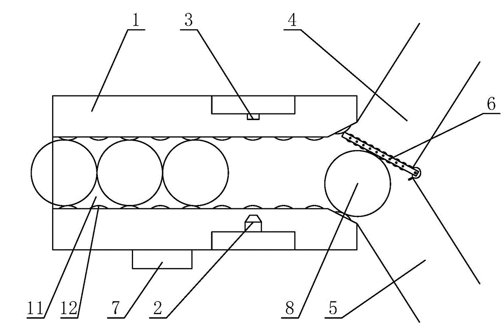
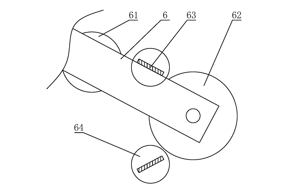
[0013] see Figure 1 ~ Figure 2 , the high and short workpiece material distribution tooling includes a transmission channel 1, and a transmission groove 11 is opened on the transmission channel 1, and the high and short workpieces 8 are placed in the transmission groove 11 for transmission, and the two transmission grooves 11 The side is provided with the conveying roller 12 that drives the high and short workpieces 8 to be conveyed in the conveying groove 11. The right side of the transmission channel 13 is provided with two laser reflectors 2 up and down, and the left side of the conveying channel 1 is equipped with a laser reflector. The receiving plate 3, the rear end of the transmission channel 1 is respectively connected with a high workpiece unloading channel 4 and a short workpiece unloadin...


PUM


Abstract

The invention discloses a high workpiece and short workpiece separating tool. The high workpiece and short workpiece separating tool comprises a conveying passage. A conveying groove is formed in the conveying passage. High workpieces and short workpieces are placed in the conveying groove so as to be conveyed. Conveying rolling wheels are arranged on the two sides of the conveying groove. Two laser reflectors are arranged on the upper portion and the lower portion of the right side of the conveying passage. A laser receiving plate is arranged on the left side of a conveying belt in a matched mode. A high workpiece discharging passage and a short workpiece discharging passage are both connected to the rear end of the conveying passage, and the high workpiece discharging passage and the short workpiece discharging passage incline downwards. A separation plate is arranged at the discharging end of the conveying passage. A driving motor is arranged at the rear end of the separation plate. A driven wheel is also arranged on the separation plate. Through holes are formed in the high workpiece discharging passage and the short workpiece discharging passage correspondingly. Baffles are arranged in the through holes. A driving component is connected to the lower end of each baffle. A controller is further arranged on the conveying passage. The controller is electrically connected with the laser receiving plate, the driving motor and the driving components. By the adoption of the high workpiece and short workpiece separating tool, the high workpieces can be automatically separated from the short workpieces.

Description

technical field [0001] The invention relates to a tool for distributing materials for tall and short workpieces. Background technique [0002] During the production of workpieces, two workpieces with different heights are produced, and the two workpieces need to be divided into materials. Traditional operations require manual division of the high and low tooling. This method of operation is time-consuming, laborious, and low in work efficiency. Contents of the invention [0003] The object of the present invention is to provide a high and low workpiece material distributing tool that can automatically materialize high and low workpieces. [0004] To achieve the above object, the present invention provides the following technical solutions: [0005] A high and short work piece material distribution tool, including a transmission channel, a transmission groove is opened on the transmission channel, the high and short workpieces are placed in the transmission groove for tran...

Claims


Application Information

Patent Timeline
Patent Type & Authority Applications(China)
IPC IPC(8): B65G47/71
Inventor 唐靖岚
Owner WUXI QINGYANG MACHINERY MFG
Why Eureka
Try Eureka