A vacuum antifreeze filling gun

A filling gun and vacuum technology, used in special distribution devices, packaging, distribution devices, etc., can solve the problems of insufficient pressure relief, water becoming, and loosening of tie rod nuts, so as to reduce the matching gap, ensure safe use, and improve sealing effect

Active Publication Date: 2018-07-24
CHENGDU ANDERSON MEASUREMENT
View PDF7 Cites 0 Cited by
  • Summary
  • Abstract
  • Description
  • Claims
  • Application Information

AI Technical Summary

Problems solved by technology

[0004] 1. Due to the ultra-low temperature of the filling medium, the temperature of the medium is maintained at -150°C to -170°C for a long time. The ultra-low temperature will spread outward through the inner sleeve, and it will be directly transmitted to the outer sleeve and the corresponding claw mechanism and positioning through the inner sleeve. ring, etc., causing the claw mechanism and the moving parts of the positioning ring to be easily frosted, and the frost will turn into water after melting, and it will freeze at low temperature when refilling, so that the filling gun will be frozen It is very difficult to extract, which affects the efficiency of work and the flexibility of operation
[0005] 2. Since the positioning ring is connected with the connecting plate and the inner casing through the tie rod, the tie rod is movable and adjustable, so the size adjustment must be carried out every time during production, and the tie rod nut may become loose during use, resulting in The size change of the filling gun body affects the change of the pressure relief position of the filling gun and the filling port, resulting in insufficient pressure relief, accidental withdrawal of the filling gun and other safety hazards

Method used


Image

  • A vacuum antifreeze filling gun
  • A vacuum antifreeze filling gun
  • A vacuum antifreeze filling gun

Examples


specific Embodiment

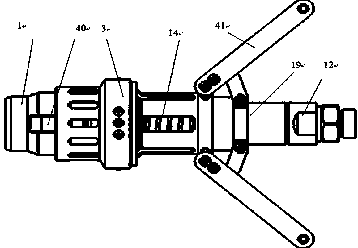
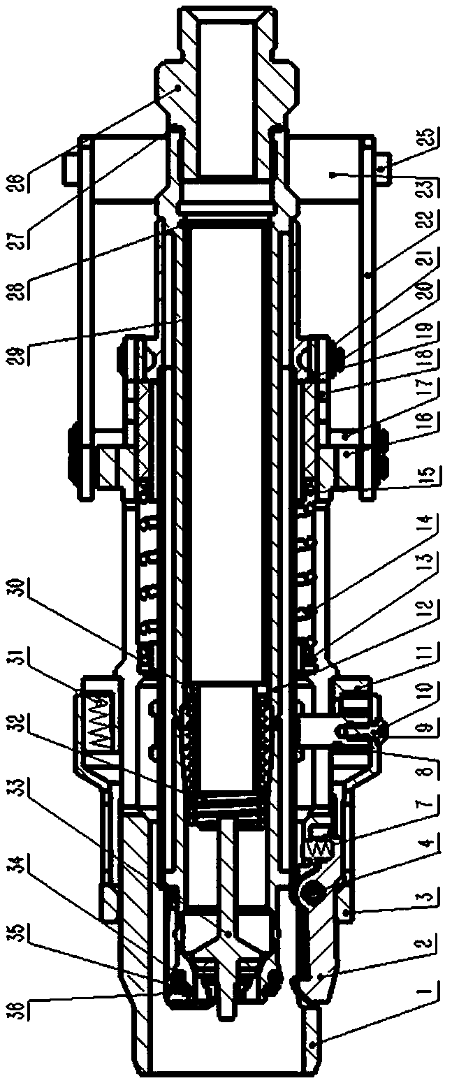
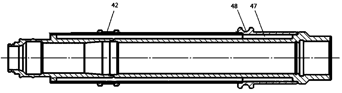
[0032] Such as Figure 1-7 As shown, a vacuum antifreeze filling gun of the present invention includes an outer casing 1, an inner casing 12, and a one-way valve core assembly; the outer casing 1 can be relatively slidably sleeved outside the inner casing 12, and the one-way valve The core assembly is hermetically installed at one end of the inner casing 12 ; a vacuum layer 47 is provided inside the wall of the inner casing 12 . The tube wall of the inner casing 12 includes a first tube wall and a second tube wall, the second tube wall is sleeved on the first tube wall, and the edge of the second tube wall sleeve is sealingly connected with the first tube wall, and is connected to the second tube wall. A vacuum layer 47 is formed between the wall and the first pipe wall, and the thickness of the vacuum layer 47 is 5-10 mm.

[0033]The rear end of the outer sleeve 1 is connected to the inner sleeve 12 through a handle mechanism 41, and a main spring 14 is arranged between the ...


PUM


Abstract

The invention relates to the technical field of low-temperature or ultralow-temperature application, in particular to a liquefied natural gas filling device, in particular to a vacuum anti-freezing filling gun. The vacuum anti-freezing filling gun comprises an outer sleeve, an inner sleeve and a one-way valve core assembly. The inner sleeve can be sleeved with the outer sleeve, and the outer sleeve can slide relative to the inner sleeve. The one-way valve core assembly is assembled at one end of the inner sleeve in a sealed manner. A vacuum layer is arranged in the sleeve wall of the inner sleeve. Due to the mechanism mentioned above, low-temperature conduction can be reduced through the vacuum layer of the inner sleeve, so that the frosting possibility and freezing possibility of handle mechanisms, a locating ring and clamping claw movement mechanisms are relieved and lowered in the filling process, and the operating flexibility is guaranteed to the maximum extent; due to the fact that a pull rod and other movable connecting components are eliminated, size adjustment of the pull rod is not needed, the size of a main body structure is more stable through the design and structure guarantee, and the potential safety hazards such as the condition that a filling gun retreats by accident due to insufficient pressure relief are eliminated; and meanwhile shaft sleeve locating is added between the inner sleeve and the outer sleeve, locating accuracy is higher, and the effect that the handle mechanisms are free of loosening, swinging and other phenomena in the use process is guaranteed, so that operation is more stable and convenient.

Description

technical field [0001] The invention relates to the technical field of low temperature or ultra-low temperature application, in particular to a filling gun for liquefied natural gas. Background technique [0002] The filling gun is one of the core components of the filling system. It is the carrier that realizes the reliable connection between the liquid filling machine, the vehicle filling port and the steel cylinder, and is used to control the flow of the filling medium to the vehicle cylinder. When the filling gun is connected, the one-way valve core of the filling gun and the one-way valve core of the filling port are pushed apart to form a medium passage, and the medium can flow smoothly; when the filling gun is separated from the filling port, The one-way valve cores of the filling gun and the filling port rely on the medium pressure and the spring force to automatically reset and seal to ensure no leakage. Before the filling gun is disengaged from the filling port, t...

Claims


Application Information

Patent Timeline
Patent Type & Authority Patents(China)
IPC IPC(8): B67D7/54
CPCB67D7/54
Inventor 宁扬忠曾学兵田隆
Owner CHENGDU ANDERSON MEASUREMENT
Why Eureka
Try Eureka