
A gas filter device placed in front of vacuum obtaining equipment

A filter device and equipment technology, applied in mechanical equipment, liquid variable volume machinery, variable volume pump components, etc., can solve the problems of short maintenance interval, single filter medium, small power-to-body ratio, etc., to achieve high work efficiency, Increased filter area and longer maintenance intervals

Active Publication Date: 2017-12-15
SHENYANG SCI INSTR RES CENT CHINESE ACAD OF SCI
View PDF5 Cites 0 Cited by
  • Summary
  • Abstract
  • Description
  • Claims
  • Application Information

AI Technical Summary

Problems solved by technology

[0003] At present, most filters adopt a single-stage, cylindrical filter element, a simple up-and-down arrangement of air intake and air outlet, a single filter medium, and no pressure monitoring.
Disadvantages are: single function, low efficiency, small power-to-body ratio, short maintenance intervals, and difficulty in cleaning the inside of the filter

Method used


Image

  • A gas filter device placed in front of vacuum obtaining equipment
  • A gas filter device placed in front of vacuum obtaining equipment

Examples


Embodiment Construction

[0019] The present invention will be described in further detail below in conjunction with the accompanying drawings.

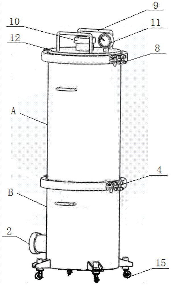
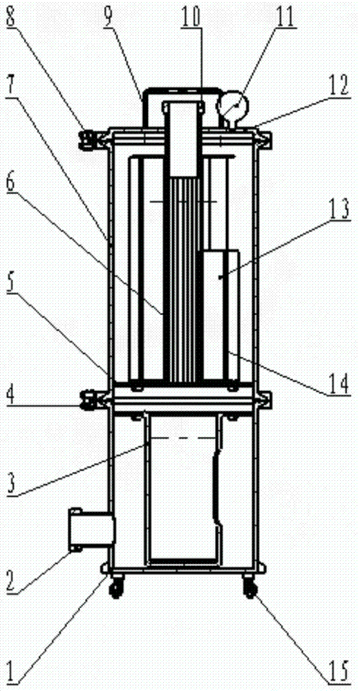
[0020] Such as figure 1 , figure 2 As shown, the present invention includes an upper-stage filter A, an intermediate connecting plate 5 and a lower-stage filter B, wherein the lower end of the lower-stage filter B is provided with a lower-stage air inlet 2, and the upper end is connected with the bottom of the upper-stage filter A through a clamp I4, The top of the upper filter A is provided with an upper exhaust port 10 , and the bottom of the lower filter B is provided with casters 15 . The intermediate connecting plate 5 is arranged at the bottom of the upper filter A, and the intermediate connecting plate 5 is provided with a plurality of through holes connecting the upper filter A and the lower filter B along the circumference. The lower air inlet 2 is connected to the pumped gas source, and the upper air outlet 10 is connected to a vacuum pump.

[0...


PUM


Abstract

The invention relates to the technical field of vacuum, in particular to a gas filtering device arranged in front of vacuum pumping equipment. The gas filtering device comprises an upper-stage filter, a middle connecting disc and a lower-stage filter. A lower-stage air inlet is formed in the lower end of the lower-stage filter. The upper end of the lower-stage filter is connected with the bottom of the upper-stage filter. An upper-stage air outlet is formed in the top of the upper-stage filter. The middle connecting disc is arranged at the bottom of the upper-stage filter. A plurality of through holes enabling the upper-stage filter to communicate with the lower-stage filter are formed in the middle connecting disc in the circumferential direction. Trundles are arranged at the bottom of the lower-stage filter. The lower-stage air inlet is connected with a pumped air source. The upper-stage air outlet is connected with a vacuum pump. The gas filtering device arranged in front of the vacuum pumping equipment is high in working efficiency, the maintenance interval is long, and the interiors of the filters can be cleaned easily.

Description

technical field [0001] The invention relates to the field of vacuum technology, in particular to a gas filtering device pre-installed in vacuum obtaining equipment. Background technique [0002] Vacuum pumps work in a wide range of fields, and the actual process is complex and changeable. If the dust, water and oil vapor contained in the pumped gas enters the vacuum pumping system, it will bring great harm to the equipment, affect production, and increase equipment maintenance costs and cycles. A gas filter in front of the pump is beneficial to protect the vacuum pump, and is also beneficial to keep the exhaust clean of the entire exhaust system. [0003] At present, most filters adopt a single-stage, cylindrical filter element, a simple up-and-down arrangement of air intake and air outlet, a single filter medium, and no pressure monitoring. The disadvantages are: single function, low efficiency, small power-to-body ratio, short maintenance intervals, and difficulty in clea...

Claims


Application Information

Patent Timeline
Patent Type & Authority Patents(China)
IPC IPC(8): F04B39/16
Inventor 王光玉汤剑李昌龙
Owner SHENYANG SCI INSTR RES CENT CHINESE ACAD OF SCI
Learn More