
Diverter valve for roof water tank of building

A technology for buildings and diversion valves, applied in valve devices, filtration separation, mechanical equipment, etc., can solve the problems that the diversion waterway does not have the filtering function and the valve core is easily damaged, so as to increase the number of times, reduce the curvature, and improve the filtration efficiency effect

Inactive Publication Date: 2016-06-08
陈杰
View PDF5 Cites 0 Cited by
  • Summary
  • Abstract
  • Description
  • Claims
  • Application Information

AI Technical Summary

Problems solved by technology

[0003] In the prior art, the diversion valve for the water tank on the roof of the building cannot automatically close and switch to the diversion state when the downstream pipeline leaks, and the diversion waterway does not have a filtering function, and the valve core is easily damaged

Method used


Image

  • Diverter valve for roof water tank of building
  • Diverter valve for roof water tank of building
  • Diverter valve for roof water tank of building

Examples


Embodiment Construction

[0018] Hereinafter, preferred embodiments of the present invention will be described in detail with reference to the accompanying drawings.

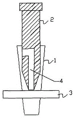
[0019] Such as figure 1 , a diversion valve for a water tank on the roof of a building is composed of a housing 1, a diversion shaft 2 and a pipeline 3, the pipeline 3 passes through the housing 1, the diversion shaft 2 is arranged in the housing 1 and can reciprocate, and the diverter One end of the flow shaft 2 is opposite to the side wall of the pipe 3, and the inside of the flow guide shaft 2 has a flow guide channel 4, the entrance of the flow guide channel 4 is arranged on the side of the flow guide shaft 2, and the outlet of the flow guide channel 4 is arranged The bottom end, and the diameter of the guide shaft 2 at the entrance of the guide channel 4 is greater than or equal to the diameter of the pipe 3 facing it, so that when the guide shaft 2 passes through the pipe 3, the pipe 3 can be completely cut off and the pipe 3 It c...


PUM


Abstract

The invention provides a diverter valve for a roof water tank of a building. The diverter valve consists of a shell (1), a diverter shaft (2) and a pipeline (3), wherein the pipeline (3) penetrates through the shell (1); the diverter shaft (2) is arranged in the shell (1) and can move in a reciprocating manner; one end of the diverter shaft (2) is opposite to the side wall of the pipeline (3); a diverter channel (4) is formed in the diverter shaft (2); an inlet of the diverter channel (4) is formed in the side face of the diverter shaft (2); the diverter shaft (2) can completely cut off the pipeline (3) when penetrating through the pipeline (3), and the pipeline (3) is communicated with the diverter channel (4); an inlet of the pipeline (3) is further connected with a filtering pipe and a connection port with an inner diameter greater than the outer diameter of the filtering pipe; and the filtering pipe is provided with a pipe body with a blocked outer end. The diverter valve has the positive effects that when the pressure of the water tank is extremely high and a downstream pipeline leaks water, the diverter shaft penetrates through the pipeline to completely cut off the pipeline and make the pipeline communicated with the diverter channel; and furthermore, the inlet of the pipeline is further connected with the filtering pipe, thus realizing a filtering function of a diverter water path.

Description

technical field [0001] The invention discloses a diversion valve, in particular to a diversion valve for a water tank on the roof of a building, belonging to the field of plumbing equipment. Background technique [0002] The water tank on the roof of the building is often provided with a diversion valve. [0003] In the prior art, the diversion valve for the water tank on the roof of the building cannot automatically close and switch to the diversion state when the downstream pipeline leaks, and the diversion waterway does not have a filtering function, and the valve core is easily damaged. Contents of the invention [0004] In view of this, the present invention provides a diversion valve for a water tank on the roof of a building, which can automatically close the diversion valve when the downstream pipeline leaks, and make the diversion waterway have a filtering function, prolonging the use of the diversion valve life. [0005] Concrete scheme of the present invention...

Claims


Application Information

Patent Timeline
Patent Type & Authority Applications(China)
IPC IPC(8): F16K13/00B01D35/04
CPCF16K13/00B01D35/04
Inventor 陈杰
Owner 陈杰
Learn More