Diversion valve

A diversion valve and valve body technology, applied in the field of diversion valves, can solve the problems of no filtering function, easy corrosion and damage of the valve body, complicated operation of the diversion valve, etc., achieving simple structure, reducing cleaning costs, and increasing the number of times. Effect

Inactive Publication Date: 2016-06-22
张作玮
View PDF6 Cites 0 Cited by
  • Summary
  • Abstract
  • Description
  • Claims
  • Application Information

AI Technical Summary

Problems solved by technology

However, in some occasions where diversion switching is infrequent and cost-sensitive, the existing diversion valve cannot meet the requirements due to the defects

Method used


Image

  • Diversion valve
  • Diversion valve
  • Diversion valve

Examples


Example Embodiment

[0020] The present invention will be further described in detail below in conjunction with the accompanying drawings.

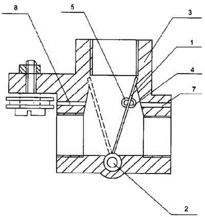
[0021] A diversion valve, characterized in that: the diversion valve has a steel valve body 3, the valve body 3 has a three-way cavity including an upper cavity, a left cavity, and a right cavity. There is a flap 1 located between the left cavity and the right cavity and below the upper cavity. The lower end of the flap 1 is hinged with the bottom wall of the valve body 3 through the flap shaft 2 and the upper end of the flap 1 has sleeves on both sides. Ring 1 4 and Ring 2 5 are provided on both sides of the valve body 3 with holes 1 7 and 2 8 for passing glass ropes. The ring 1 4 is connected with the glass rope in the hole 1 7. The second ring 5 is connected to the glass rope in the second hole 8;

[0022] The upper cavity is connected with the inlet, the left cavity is connected with the left outlet, and the right cavity is connected with the right outlet;

[...


PUM


Abstract

The invention discloses a diversion valve which comprises a valve body (3); the valve body (3) is provided with a three-way inner cavity comprising an upper inner cavity, a left inner cavity and a right inner cavity; a turnover plate (1) positioned between the left inner cavity and the right inner cavity and positioned under the upper inner cavity is arranged in the inner cavity, the lower end of the turnover plate (1) is hinged to the bottom wall of the valve body (3) through a turnover plate shaft (2), and a ferrule I (4) and a ferrule II (5) are respectively arranged on the two sides of the upper end of the turnover plate (1); a hole I (7) and a hole II (8) for allowing a glass rope to thread through are respectively formed in the two sides of the valve body (3); the ferrule I (4) is connected with the glass rope in the hole I (7); the ferrule II (5) is connected with the glass rope in the hole II (8); the upper inner cavity is connected with an inlet; the inlet is connected with a filtering pipe and a connecting port of which the internal diameter is larger than the external diameter of the filtering pipe. The diversion valve disclosed by the invention is simple in structure, convenient to operate and low in cost and has a filtering function, and the valve body is not easy to damage.

Description

technical field [0001] The invention relates to a valve, in particular to a diversion valve. Background technique [0002] In many industrial situations, it is necessary to use diverter valves to introduce water flow into different pipes. [0003] Most of the existing diversion valves are electrically controlled. However, in some occasions where diversion switching is infrequent and cost-sensitive, the existing diversion valve cannot meet the requirements due to the defects of cumbersome operation and high cost, and it does not have a filtering function, and the inside of the valve body is easily corroded and damaged. Low service life. Contents of the invention [0004] The purpose of the present invention is to provide a diversion valve with simple structure, good operability, low cost and long service life. [0005] Technical scheme of the present invention is as follows: [0006] A diversion valve has a valve body, the valve body has a three-way inner cavity includi...

Claims


Application Information

Patent Timeline
IPC IPC(8): F16K11/04F16K27/02
CPCF16K11/04F16K27/02
Inventor 张作玮
Owner 张作玮
Why Eureka
Try Eureka