Supercharge Your Innovation With Domain-Expert AI Agents!

An adaptive energy harvesting device and method

A self-adaptive and energy technology, applied in circuit devices, parallel operation of DC power supplies, electrical components, etc., can solve the problems of reduced safety of circuit devices, reduced safety, limited output energy of the secondary winding of current transformers, etc. The effect of high energy efficiency and reduced power line current requirements

Active Publication Date: 2018-08-14
苏州银蕨电力科技有限公司
View PDF4 Cites 0 Cited by
  • Summary
  • Abstract
  • Description
  • Claims
  • Application Information

AI Technical Summary

Problems solved by technology

[0003] Due to the relatively large variation range of the current on the power line, there are technical difficulties in the self-induction energy harvesting method of the current transformer, which is mainly reflected in that when the power line current is small, the output energy of the secondary winding of the current transformer is limited. The current transformer obtains enough energy to make the subsequent circuit work, so the volume of the current transformer must be increased, which will greatly increase the volume and weight of the entire power-taking device, and greatly reduce the safety of the entire device installed on the overhead line , or cause the post-stage circuit to fail to work when the power line current is small; when the power line current is large, the output energy of the secondary winding of the current transformer is very large, and the energy induced by the current transformer may exceed the energy required for the post-stage circuit to work. If the energy is not safely released, the safety of the circuit and the entire device will be greatly reduced

Method used


Image

  • An adaptive energy harvesting device and method
  • An adaptive energy harvesting device and method

Examples


Embodiment Construction

[0039] In view of the deficiencies in the prior art, the inventor of this case was able to propose the technical solution of the present invention after long-term research and extensive practice. The technical solution, its implementation process and principle will be further explained as follows.

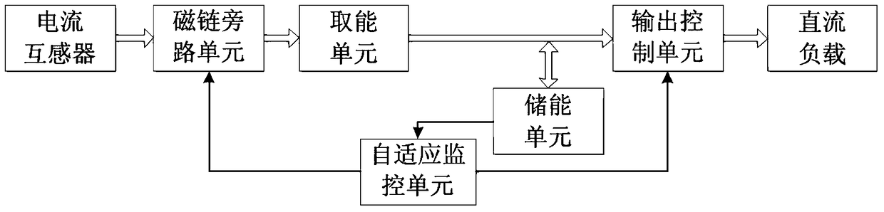
[0040] The adaptive energy harvesting device described in this embodiment is shown in the figure figure 1 As shown, when there is current flowing in the power line, an induced current will be generated in the secondary winding of the current transformer, and the secondary winding of the transformer is connected to the flux linkage bypass unit. The flux bypass unit is controlled by the adaptive monitoring unit. When the flux bypass unit is turned on, the secondary winding of the transformer is short-circuited, and the energy will not be transmitted to the following modules; when the flux bypass unit is turned off, the secondary winding of the transformer Connect directly to the ene...


PUM


Abstract

The invention discloses a power-grid adaptive energy taking apparatus. The apparatus comprises a current transformer, a flux linkage bypass unit, an energy taking unit, an energy storage unit, an output control unit and an adaptive monitoring unit. A requirement of the energy taking apparatus to a power line current is reduced. According to energy of the energy storage unit, adaptive switching among different work modes can be rapidly performed and energy taking efficiency is high. The invention also discloses a power-grid adaptive energy taking apparatus. In the method, the adaptive monitoring unit is arranged in the energy taking apparatus to monitor the energy of the energy storage unit in real time; the energy of the energy storage unit is compared with energy required by a backward-stage direct current load so as to determine a work mode of the energy taking apparatus. Through the adaptive monitoring unit, open and close of the flux linkage bypass unit and the output control unit are controlled to realize switching of the different work modes. In an existing power line energy taking technology, the power line can not work under a low current and excess energy taking under a heavy current is generated. By using the apparatus and the method of the invention, the above problems are solved and a potential safety hazard is avoided.

Description

technical field [0001] The invention belongs to the technical field of energy extraction on the side of an AC power grid, and in particular relates to a power grid self-adaptive energy harvesting device and method. Background technique [0002] If the sensing device of the existing smart grid is installed on the overhead line, it is difficult to use a conventional power supply due to insulation problems. The self-induction energy harvesting of current transformer is a better way to solve the power supply of this kind of device. On the one hand, it can realize the self-power supply of the device, and on the other hand, it can achieve the equipotential between the device and the power line, which solves the insulation problem and facilitates installation. [0003] Due to the relatively large variation range of the current on the power line, there are technical difficulties in the self-induction energy harvesting method of the current transformer, which is mainly reflected in t...

Claims


Application Information

Patent Timeline
Patent Type & Authority Patents(China)
IPC IPC(8): H02J1/10H02J50/10
Inventor 朱志明方明倪贵成
Owner 苏州银蕨电力科技有限公司
Features
  • R&D
  • Intellectual Property
  • Life Sciences
  • Materials
  • Tech Scout
  • Unparalleled Data Quality
  • Higher Quality Content
  • 60% Fewer Hallucinations
Learn More