Supercharge Your Innovation With Domain-Expert AI Agents!

Control of a dual rotor electromagnetic machine

a dual-rotor electromagnetic machine and control technology, applied in the direction of stator/rotor body manufacturing, magnetic circuit shape/form/construction, magnetic circuits, etc., can solve the problems of increasing the current capacity of electronics, reducing and requiring electrical power loss and heat, so as to reduce the current requirement of machines.

Inactive Publication Date: 2010-09-21
DEERE & CO
View PDF17 Cites 1 Cited by
  • Summary
  • Abstract
  • Description
  • Claims
  • Application Information

AI Technical Summary

Benefits of technology

The present invention provides a dual rotor electromagnetic machine with a mechanism for adjusting the rotor relative angular displacement that is simple and inexpensive. The machine can operate while running and can carry high torque loads. The coupling mechanism is a planetary transmission with a fixed ring gear and a movable ring gear, which automatically adjusts the angular alignment between the two rotors during operation of the machine to maximize the back EMF at both the base speed and the maximum speed. The manufacturing method involves determining the different separate rotor lengths for each rotor based on the desired base speed and maximum speed, and increasing the number of coils based on the back EMF at the base speed to decrease the current requirement of the machine.

Problems solved by technology

This current creates electrical power losses and heat, and requires the electronics to have an increased current capacity.
However, none of these machines appears to have a mechanism for adjusting the rotor relative angular displacement which is simple, inexpensive, capable of operating while the machine is running and which can carry high torque loads.
Furthermore, none of these machines use rotors which provide a back EMF with the rotors aligned at 180 degrees to each other.

Method used


Image

  • Control of a dual rotor electromagnetic machine
  • Control of a dual rotor electromagnetic machine
  • Control of a dual rotor electromagnetic machine

Examples


Embodiment Construction

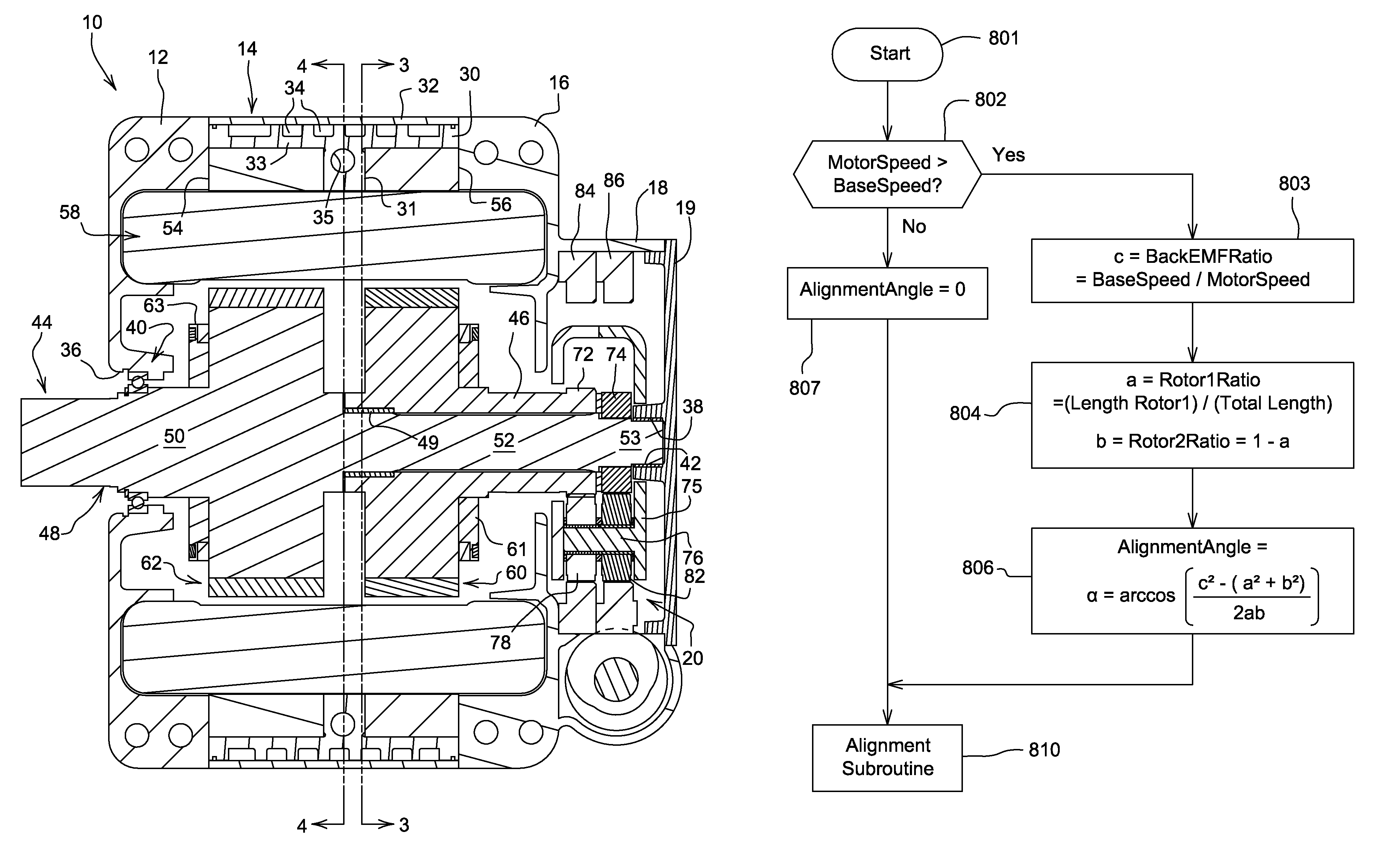
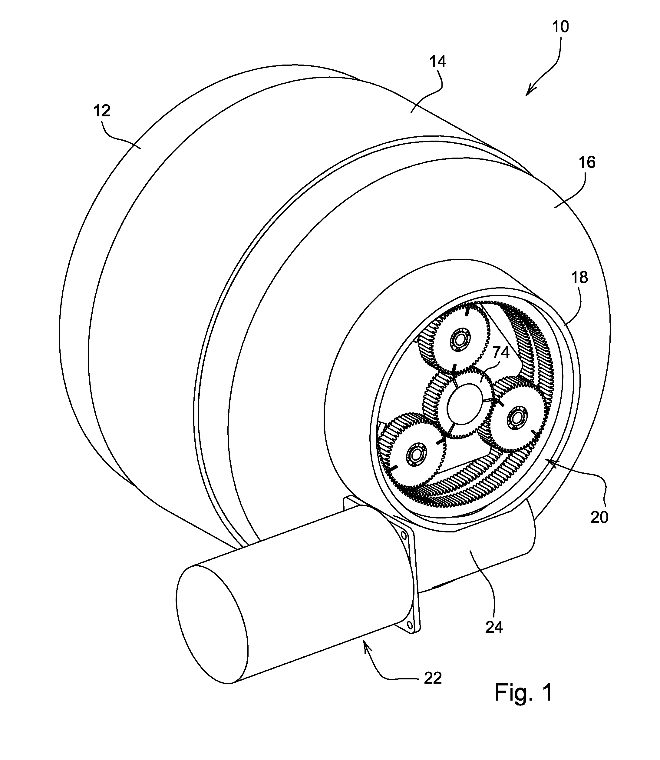
[0028]Referring to FIG. 1, a multi-rotor synchronous electromagnetic machine 10 has a housing 11 which includes a first end housing 12, a center housing 14 and a second end housing 16. A cylindrical housing ring 18 projects from an end of the housing 16 and surrounds a planetary gear mechanism 20. An actuator 22 with a worm gear 24 is attached to the housing ring 18.

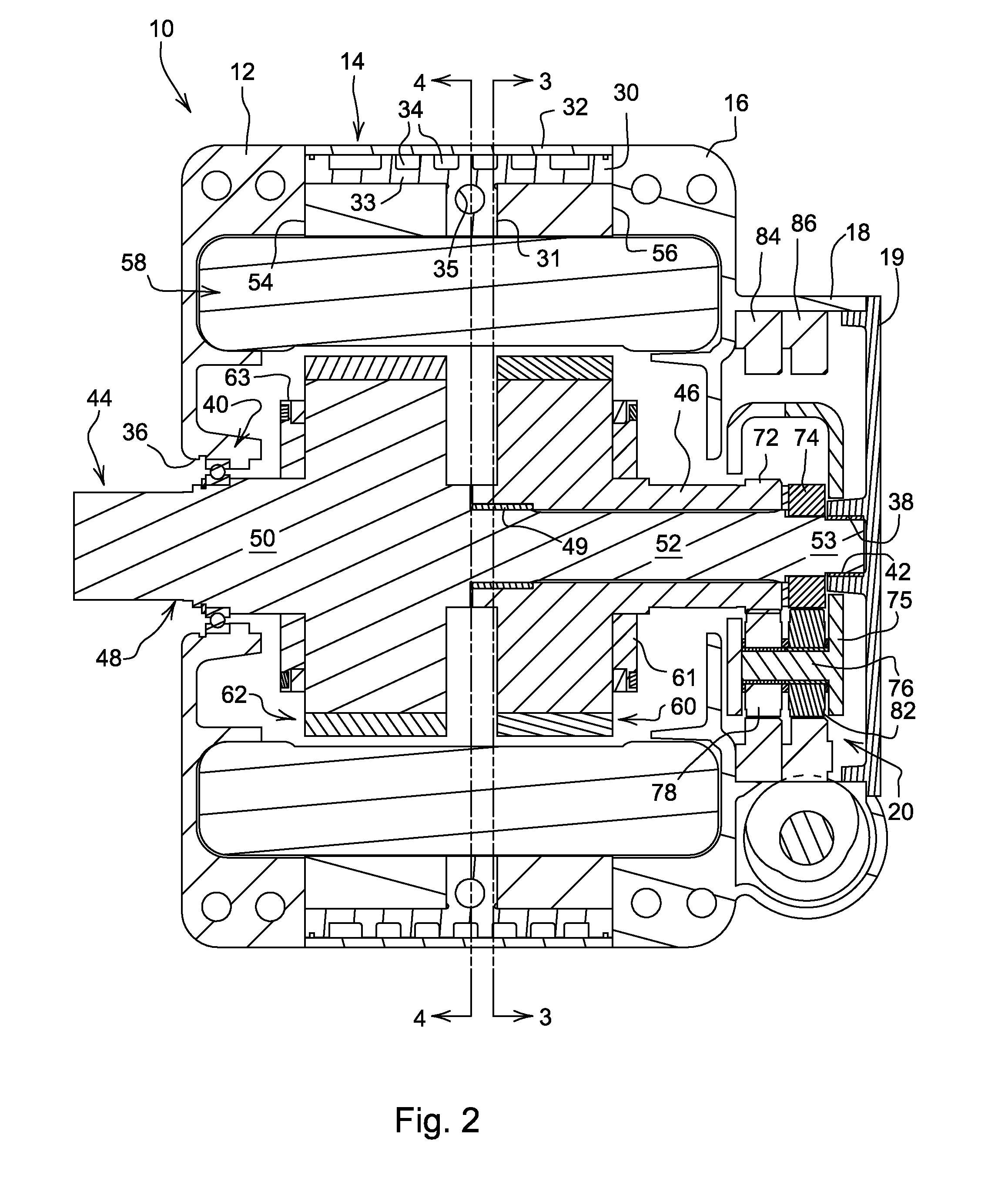
[0029]Referring now to FIG. 2, the center housing 14 has an inner sleeve 30 and an outer sleeve 32. An end plate 19 covers the housing ring 18. A plurality of water cooling channels 34 are formed in the outer peripheral surface of inner sleeve 30, and these channels 34 are covered and sealed by the outer sleeve 32. Sleeve 30 preferably has a T-shaped cross sectional shape and is formed of a heat conducting material, such as aluminum. Sleeve 30 has an annular central leg 31 which projects radially inwardly from an inner surface of cylindrical rim 33. End housing 12 has a central opening 36. End plate 19 forms a central bl...


PUM

PropertyMeasurementUnit
index angleaaaaaaaaaa
angleaaaaaaaaaa
lengthaaaaaaaaaa

Abstract

The invention relates to an electric synchronous machine. There is a need for a dual rotor electric synchronous machine which has a mechanism for adjusting the rotor relative angular displacement while the machine is running in order to reduce back EMF. There is a need for such an adjusting mechanism which can carry high torque loads. An electric synchronous machine is provided with a housing, first and second shafts rotatably supported in the housing, each with a corresponding rotor fixed thereon, both having permanent magnet field poles. Each rotor is surrounded by a corresponding annular stator, and stator coils are wound through both stators. A planetary transmission is coupled between the first and second shafts and operable during rotation of the first and second shafts to adjust an angular orientation of the second shaft with respect to the first shaft.

Description

CROSS-REFERENCE TO RELATED APPLICATION[0001]This is a Continuation-in-Part application of application Ser. No. 11 / 588,546 titled “Dual Rotor Electromagnetic Machine” by Ronald D Bremner, filed on Oct. 26, 2006 now U.S. Pat. No. 7,576,465 and having a common inventor and commonly owned at the time of the invention.FIELD OF THE INVENTION[0002]The present invention relates to brushless permanent magnet motors and generators, especially those which must operate over a wide speed range, such as those used in hybrid vehicles or machine tools. More specifically, the present invention relates to the control of such motor during operation of the motor.BACKGROUND OF THE INVENTION[0003]Brushless permanent magnet motors have a back-EMF that is proportional to their speed. At high speeds, the back-EMF of the motor can be much higher than the power supply can deliver. Above this speed, additional current out of phase with the back-EMF must be added in order to weaken the magnetic field of the mot...

Claims


Application Information

Patent Timeline
Patent Type & Authority Patents(United States)
IPC IPC(8): H02K15/02H02K15/10
CPCH02K21/029H02K7/116H02K16/02Y10T29/49012Y10T29/49073Y10T29/49009H02K2201/06
Inventor BREMNER, RONALD DEAN
Owner DEERE & CO
Features
  • R&D
  • Intellectual Property
  • Life Sciences
  • Materials
  • Tech Scout
  • Unparalleled Data Quality
  • Higher Quality Content
  • 60% Fewer Hallucinations
Learn More