Supercharge Your Innovation With Domain-Expert AI Agents!

Light emitting device driving circuit and method thereof

A technology of light-emitting components and drive circuits, which is applied in the direction of electrical components, lamp circuit layout, light sources, etc., can solve the problems of image flickering and other problems, and achieve the effect of improving quality and avoiding flickering phenomenon

Inactive Publication Date: 2016-06-08
KINPO ELECTRONICS +1
View PDF4 Cites 1 Cited by
  • Summary
  • Abstract
  • Description
  • Claims
  • Application Information

AI Technical Summary

Problems solved by technology

[0005] The invention provides a light-emitting element driving circuit and its method, which can actively detect the light source frequency of the light-emitting element in the environment, and adjust according to it, so as to improve the problem of flickering on the image screen when acquiring images

Method used


Image

  • Light emitting device driving circuit and method thereof
  • Light emitting device driving circuit and method thereof
  • Light emitting device driving circuit and method thereof

Examples


Embodiment Construction

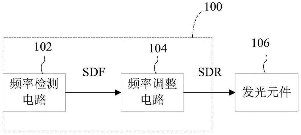
[0043] figure 1 It is a schematic diagram of a light-emitting element driving circuit according to an embodiment of the present invention, please refer to figure 1 . The light-emitting element driving circuit 100 is used to drive the light-emitting element 106 to generate an illumination source. The light emitting device driving circuit 100 includes a frequency detection circuit 102 and a frequency adjustment circuit 104 . The frequency detection circuit 102 is used for detecting the light source frequency of the light emitting element 106 to provide a detection frequency signal SDF. The frequency adjustment circuit 104 is coupled to the frequency detection circuit 102 and the light emitting element 106 . The frequency adjustment circuit 104 can output the driving signal SDR to the light emitting element 106 according to the detection frequency signal SDF and a plurality of preset blinking frequencies, so as to adjust the light source frequency of the light emitting element...


PUM


Abstract

A light emitting device driving circuit and a method thereof are provided. The light emitting device driving circuit includes a frequency detection circuit and a frequency adjustment circuit. The frequency detection circuit is configured to detect a light frequency of a light emitting device to provide at least one detection frequency signal. The frequency adjustment circuit adjusts the light frequency of the light emitting according to the detection frequency signal and a plurality of preset flicker frequencies.

Description

technical field [0001] The present invention relates to a driving circuit, and in particular to a light-emitting element driving circuit and a method thereof. Background technique [0002] In recent years, various lighting devices or lamps in the living environment gradually adopt light emitting diodes (light emitting diodes, referred to as LEDs) as light emitting elements to generate lighting sources. Light-emitting diodes have the advantages of power saving, long service life, environmental protection, and small size. Therefore, they have been widely used in various devices, such as lighting equipment, display equipment, and light sources for mobile electronic products. They have become both energy-saving and environmentally friendly. main lighting source. [0003] In the case of image acquisition in an environment where lighting sources are generated by lighting equipment or lamps, the electronic device with image acquisition function usually uses a charge-coupled device...

Claims


Application Information

Patent Timeline
Patent Type & Authority Applications(China)
IPC IPC(8): H05B37/02
CPCH05B45/22
Inventor 章钧杰林岳丰林育达
Owner KINPO ELECTRONICS
Features
  • R&D
  • Intellectual Property
  • Life Sciences
  • Materials
  • Tech Scout
  • Unparalleled Data Quality
  • Higher Quality Content
  • 60% Fewer Hallucinations
Learn More