
Automobile parking brake mounting bracket structure

A technology for installing brackets and car hands, applied in the direction of manual starting devices, etc., can solve the problems of not being able to increase the transmission of side impact force, the workload of parts modification, and the inability to improve the front seats, etc., so as to solve the difficulty of stamping and improve the Overall rigidity, the effect of improving rigidity

Inactive Publication Date: 2016-06-15
CHONGQING CHANGAN AUTOMOBILE CO LTD
View PDF6 Cites 0 Cited by
  • Summary
  • Abstract
  • Description
  • Claims
  • Application Information

AI Technical Summary

Problems solved by technology

[0006] (1) Due to the narrow layout space and many structural restrictions, the structural adjustment is inflexible. During the design process, when the handbrake installation position is fine-tuned, it is usually necessary to modify the central channel of the front floor and its reinforcement plate, and the workload of parts modification is large;
[0007] (2) The handbrake installation structure has no connection effect on the front seat rear beam assembly (left), the front floor central channel and its reinforcement plate, and the front seat rear beam assembly (right), and cannot raise the front seat rear beam assembly. The stiffness of the installation point and the bending and torsion mode of the whole vehicle cannot increase the side impact force transmission here
But do not solve the problem that above-mentioned three kinds of handbrake installation structures exist

Method used


Image

  • Automobile parking brake mounting bracket structure
  • Automobile parking brake mounting bracket structure
  • Automobile parking brake mounting bracket structure

Examples


Embodiment Construction

[0028] The present invention will be further described below in conjunction with the accompanying drawings.

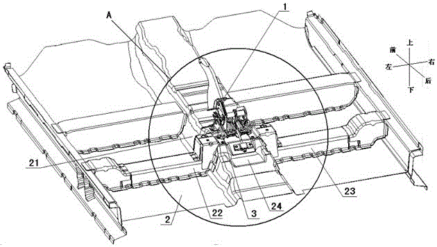
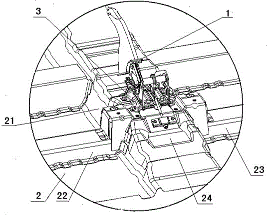
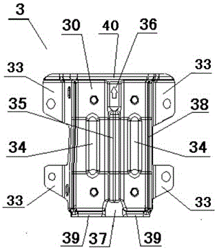
[0029] see figure 1- Figure 6 The shown car handbrake mounting bracket structure includes a handbrake 1, a front floor assembly 2 and a handbrake bracket 3; the front floor assembly 2 includes a front floor central passage 21, a reinforcement plate connected to the rear of the front floor central passage 24. The left rear crossbeam assembly 22 of the front row seat and the right rear crossbeam assembly 23 of the front row seat have a prominent substantive feature: there is a front protrusion on the front part of the reinforcing plate 24, the front The left side and the right side above the protrusion are respectively provided with a rear mounting point 25; a rear protrusion is provided at the rear of the front floor central channel 21, and a front mounting point is respectively provided on the left side and the right side of the rear protrusion 26. The left side of ...


PUM


Abstract

The invention relates to an automobile parking brake mounting bracket structure which comprises a parking brake, a front floor assembly and a parking brake bracket, wherein the front floor assembly comprises a front floor center channel, a reinforcement plate, a left rear cross beam assembly of the front seats and a right rear cross beam assembly of the front seats; a front bulge is arranged at the front part of the reinforcement plate; a rear mounting point is arranged on the front bulge; a rear bulge is arranged at the rear part of the front floor center channel; a front mounting point is arranged on the rear bulge; the whole parking brake bracket takes the shape of a frog, and four parking brake mounting faces are fixedly connected to the front floor assembly; the parking brake is fixedly connected with the parking brake bracket through bolts. The automobile parking brake mounting bracket structure can meet both the requirement on parking brake mounting and supporting and the requirement on the mounting stability of the parking brake; the design flexibility can be improved; furthermore, the rigidity of the rear mounting point of the front seats and the bending torsion mode of the whole automobile can be improved, and the effect of a connecting part on side collision force transmission is enhanced.

Description

technical field [0001] The invention belongs to an automobile braking system, and in particular relates to an automobile handbrake installation bracket structure. Background technique [0002] In the braking system of modern automobiles, the hand brake is generally installed directly on the front floor center channel in the front floor assembly or on the front floor center channel reinforcement plate. For example, CN202038301U discloses "a kind of handbrake", which is installed on the vehicle body floor. part, one end of which is fixedly connected to the handbrake guide and partly wound around the parking cable of the handbrake guide plate, and a reversing piece hinged at the base of the handbrake base, the handbrake lever and the handbrake guide Fixedly connected, the reversing member is connected with the parking cable so that the extending direction of the parking cable bends to form a bend. By hinged the reversing member at the base of the handbrake base, the parking c...

Claims


Application Information

Patent Timeline
IPC IPC(8): B60T7/10
CPCB60T7/10
Inventor 王祥王灿阳李瑛施雷李可王有传尚广先曹杰蒋伯富
Owner CHONGQING CHANGAN AUTOMOBILE CO LTD
Learn More