

Control method and electronic equipment
A technology of electronic equipment and control method, which is applied in the electronic field, can solve problems such as weak control ability, and achieve the effect of improving control ability and strong versatility
- Summary
- Abstract
- Description
- Claims
- Application Information
AI Technical Summary
Problems solved by technology
Method used
Image

Examples
Embodiment 1
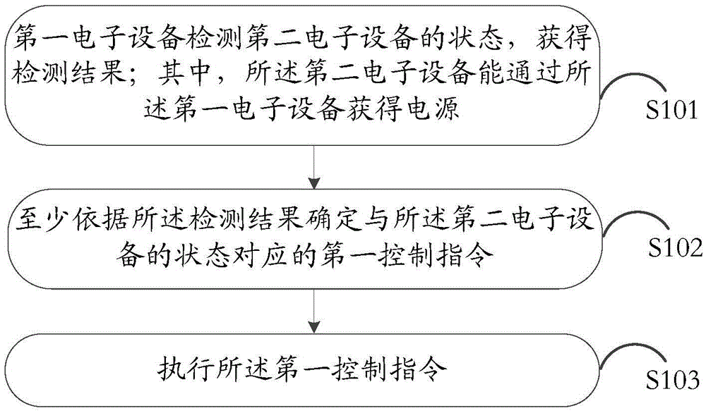
[0072] Please refer to figure 1 , is a control method provided in Embodiment 1 of the present application, including:
[0073] S101: The first electronic device detects the state of the second electronic device, and obtains a detection result; wherein, the second electronic device can obtain power through the first electronic device;
[0074] S102: Determine a first control instruction corresponding to the state of the second electronic device at least according to the detection result;
[0075] S103: Execute the first control instruction.
[0076] A control method provided in the embodiment of the present application can be applied to electronic devices such as smart sockets and charging treasures, or other electronic devices that can provide power, and is not specifically limited in the embodiments of the present application.
[0077] In the embodiment of the present application, step S101 is first performed: the first electronic device detects the state of the second elec...
Embodiment 2
[0130] The embodiment of this application also provides an electronic device, please refer to Figure 5 ,include:
[0131] housing 50;
[0132] The power-taking interface 51 is arranged on the housing 50, and the electronic device obtains power through the power-taking interface;
[0133] At least one power supply interface 52 is arranged on the housing 50, and when the power-taking interface of the second electronic device is connected to the power supply interface, the second electronic device can obtain the power supply through the electronic device;
[0134] A collection device 53 is arranged in the housing 50 and connected to the power supply interface, and is used to collect the state of the second electronic device;
[0135] The processing device 54 is arranged in the housing 50 and connected to the collection device, and is used to control the collection device to collect the state of the second electronic device and obtain a detection result; a first control instru...
Embodiment 3
[0166] The embodiment of this application also provides an electronic device, please refer to Figure 6 ,include:
[0167] The first detection unit 60 is configured to detect the state of the second electronic device and obtain a detection result; wherein, the second electronic device can obtain electric energy through the first electronic device;
[0168] The first determining unit 61 is configured to determine a first control instruction corresponding to the state of the second electronic device at least according to the detection result;
[0169] The first execution unit 62 is configured to execute the first control instruction.
[0170] Optionally, the first detection unit 60 includes:
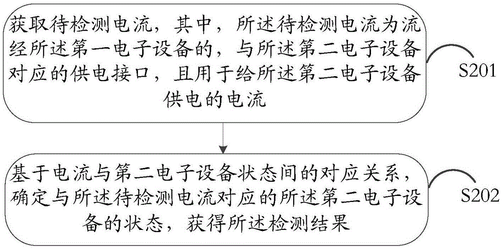
[0171] The first obtaining module is used to obtain the current to be detected, wherein the current to be detected is a power supply interface corresponding to the second electronic device that flows through the first electronic device, and is used to supply the current to the second ele...
PUM
 Abstract
Description
Claims
Application Information