

Display screen and crack detection method thereof
A technology of crack detection and display screen, which is applied in the direction of measuring devices, static indicators, electromagnetic measuring devices, etc., can solve the problems of increasing the time and cost of module manufacturing and not being able to do it at the same time, so as to save time and cost, and the detection process is intuitive Effect
- Summary
- Abstract
- Description
- Claims
- Application Information
AI Technical Summary
Problems solved by technology
Method used
Image

Examples
Embodiment 1
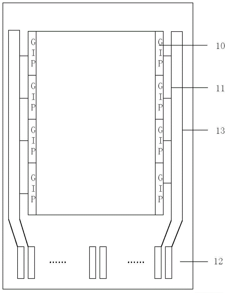
[0029] Please refer to figure 2 , which is a schematic structural diagram of the display screen provided by Embodiment 1 of the present invention. like figure 2 As shown, the display screen includes a substrate, a GIP signal line 11 and a terminal portion 12 disposed on the substrate, and a detection signal line 13 for detecting cracks in the display screen, and the detection signal line 13 is disposed on the substrate , located between the GIP signal line 11 and the edge of the substrate, one end of the detection signal line 13 is connected to the GIP signal line 11, and the other end is connected to the terminal portion 12; meanwhile, the The GIP signal line 13 connects the GIP unit 10 provided on the display screen with the terminal portion 12 .
[0030] In this embodiment, the GIP unit 10 is arranged on two sides of the display screen adjacent to the terminal portion 12, and a GIP signal line 11 and a GIP signal line 11 are respectively arranged on the two sides. A de...
Embodiment 2
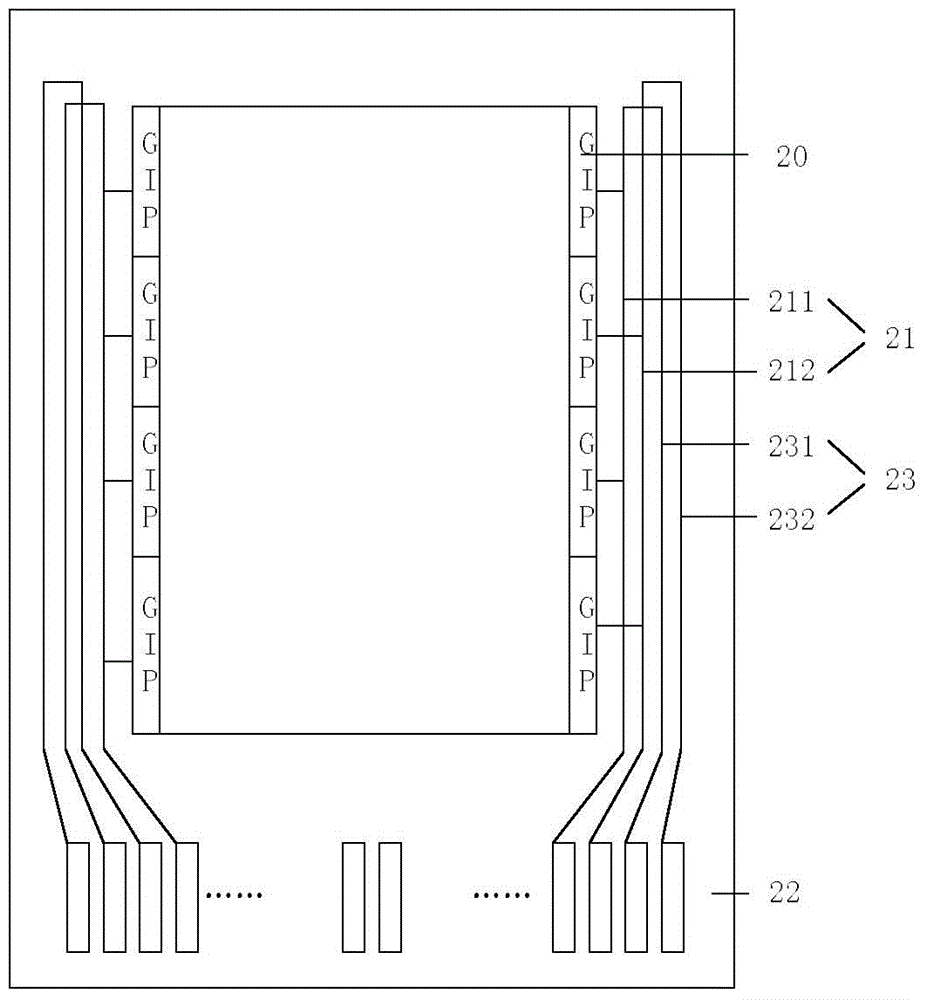
[0034] Please refer to image 3 , which is a schematic structural diagram of the display screen provided by Embodiment 2 of the present invention. like image 3 As shown, the display screen includes a substrate, a GIP signal line 21 and a terminal portion 22 disposed on the substrate, and a detection signal line 23 for detecting cracks in the display screen, and the detection signal line 23 is disposed on the substrate Above, between the GIP signal line 21 and the edge of the substrate, one end of the detection signal line 23 is connected to the GIP signal line 21, and the other end is connected to the terminal part 22; meanwhile, the The GIP signal line 23 connects the GIP unit 20 provided on the display screen with the terminal part 22 .
[0035] In this embodiment, the GIP unit 20 is arranged on two sides of the display screen adjacent to the terminal portion 22, and two GIP signal lines 211 are respectively arranged on the two sides , 212 and two detection signal lines ...
Embodiment 3
[0040] On the basis of the first embodiment, the GIP signal line and the detection signal line extend to a side opposite to the terminal portion, and are connected on a side opposite to the terminal portion.
[0041] Please refer to Figure 4 , which is a schematic structural diagram of the display screen provided by Embodiment 3 of the present invention. like Figure 4 As shown, the display screen includes a substrate, a GIP signal line 31 and a terminal portion 32 disposed on the substrate, and a detection signal line 33 for detecting cracks in the display screen, and the detection signal line 33 is disposed on the substrate Above, between the GIP signal line 31 and the edge of the substrate, one end of the detection signal line 33 is connected to the GIP signal line 31, and the other end is connected to the terminal part 32; meanwhile, the The GIP signal line 33 connects the GIP unit 30 provided on the display screen with the terminal portion 32 .
[0042] In this embodi...
PUM
 Abstract
Description
Claims
Application Information