Switching device

A switch device and switch unit technology, applied in electrical switches, mechanical control devices, devices for preventing/restricting/restoring the movement of parts of a control mechanism, etc. Effects that are convenient and easy to locate and operate

Active Publication Date: 2016-06-15
SCHNEIDER ELECTRIC (AUSTRALIA) PTY LTD
View PDF7 Cites 2 Cited by
  • Summary
  • Abstract
  • Description
  • Claims
  • Application Information

AI Technical Summary

Problems solved by technology

This results in an unattractiv

Method used


Image

  • Switching device
  • Switching device
  • Switching device

Examples


Embodiment Construction

[0029] Reference will now be made to embodiments of the disclosure, one or more examples of which are illustrated in the accompanying drawings. The examples are provided by way of illustration of the disclosure and are not intended as limitations of the disclosure. For example, features illustrated or described as part of one embodiment may be used in another embodiment to yield a further embodiment. This disclosure is intended to embrace these and other modifications and variations that are within the scope and spirit of this disclosure.

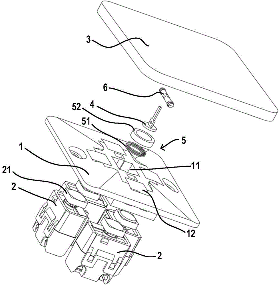
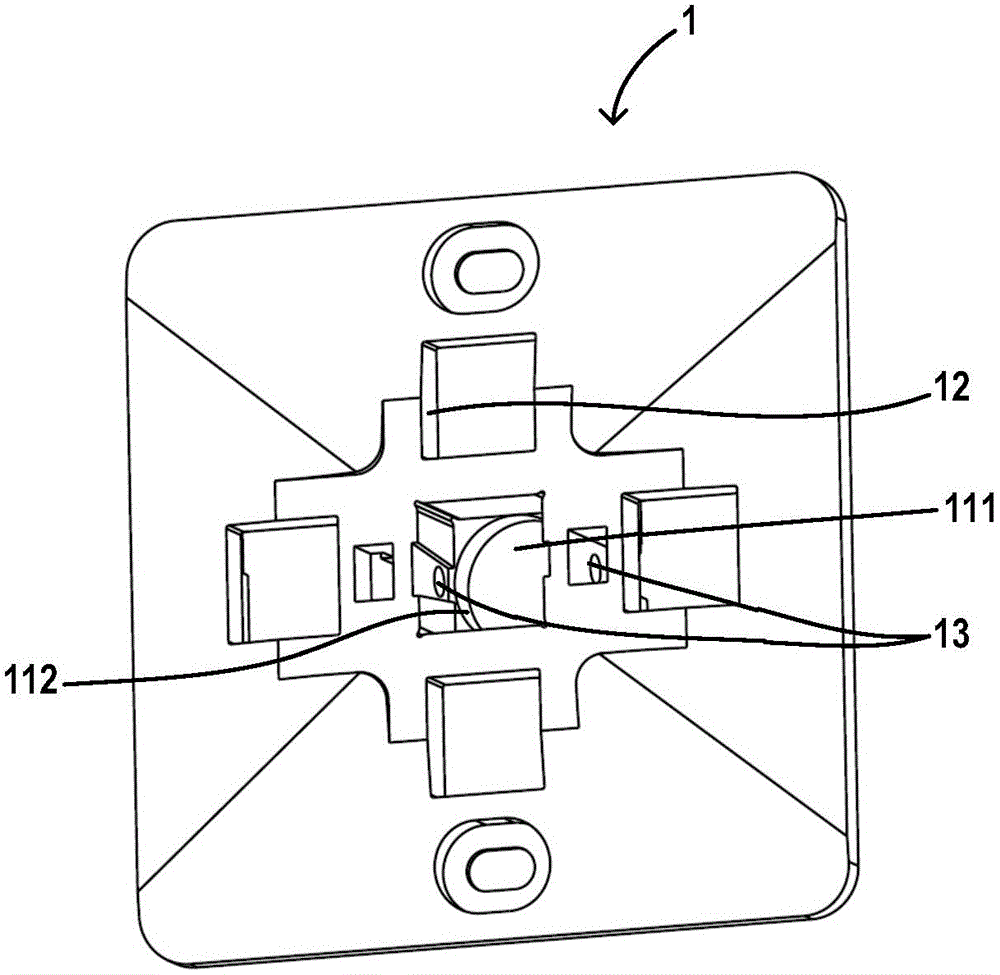
[0030] figure 1 is an exploded view of a switchgear according to an embodiment of the present disclosure. The switch device includes a base body 1 , and the center of the base body 1 is provided with a support groove 11 perpendicular to the end surface of the base body 1 . A plurality of through holes 12 are distributed around the support groove 11, at least one switch unit 2 ( figure 1 There are four of them) can be installed to the ba...


PUM


Abstract

The disclosure provides a switching device. The switching device comprises a base (1), an operation panel (3) and a reset mechanism (5), wherein a plurality of switching units (2) are arranged on the base (1), the operation panel (3) is movably connected with the base (1) by a support rod (4) so that the operation panel (3) can be operated to incline relative to the base (1) in a plurality of different directions so as to press each of the plurality of switching units (2), the reset mechanism (5) is configured to drive the operation panel (3) to recover to a balanced state from an arbitrary inclining state relative to the base (1), and in the balanced state, arbitrary one of the plurality of switching units (2) is not pressed by the operation panel (3). The switching device is attractive in appearance and is convenient to operate.

Description

technical field [0001] Embodiments of the present disclosure relate to switching devices, in particular switching devices for controlling a plurality of switching units. Background technique [0002] The current mechanical switch device usually uses one switch button to control one switch unit, and at most uses one switch button to control two switch units. However, if it is desired to control multiple switch units in one switch device, usually a plurality of switch buttons are arranged in parallel in one switch device to operate different switch units respectively. There are gaps between the switch keys arranged together, and the widths of the gaps may be different, and the inclination angles of the switch keys may also be inconsistent. This results in an unattractive appearance of the switchgear. Moreover, arranging a plurality of switch keys on a limited surface of the switch device results in a smaller surface area of ​​each key, which is not conducive to the user's co...

Claims


Application Information

Patent Timeline
IPC IPC(8): H01H25/04
CPCH01H25/04G05G1/02G05G5/05G05G9/02H01H25/041H01H2025/046
Inventor 孟环彬张大海
Owner SCHNEIDER ELECTRIC (AUSTRALIA) PTY LTD
Why Eureka
Try Eureka