
Radiating equipment

A technology of heat dissipation equipment and pressure, applied in cooling/ventilation/heating transformation, modification with liquid cooling, etc. Effect

Active Publication Date: 2016-06-15
HUAWEI TECH CO LTD
View PDF3 Cites 36 Cited by
  • Summary
  • Abstract
  • Description
  • Claims
  • Application Information

AI Technical Summary

Problems solved by technology

[0002] In the future 5G technology, hardware equipment will be highly integrated, coupled with many requirements such as product miniaturization, high heat flux density and uniform temperature of devices, the existing heat dissipation equipment will not be able to meet the heat dissipation needs of future products
For example, the existing straight-tooth radiators or die-cast straight-tooth radiators are bulky, heavy, difficult to disassemble, and have the disadvantages of uneven heat dissipation and low heat dissipation efficiency
The loop gravity heat pipe (Loop Thermosiphon, LTS) radiator adopts phase change heat dissipation technology, and the heat dissipation performance of the LTS radiator is improved compared with the die-cast radiator, but the volume and weight are still large, and it cannot be miniaturized and light. Quantify
Moreover, due to the external piping of the LTS radiator, the heat dissipation efficiency of the heat dissipation substrate is limited

Method used


Image

  • Radiating equipment
  • Radiating equipment
  • Radiating equipment

Examples


Embodiment Construction

[0051] The following will clearly and completely describe the technical solutions in the embodiments of the present invention with reference to the accompanying drawings in the embodiments of the present invention. Obviously, the described embodiments are some of the embodiments of the present invention, but not all of them. Based on the embodiments of the present invention, all other embodiments obtained by persons of ordinary skill in the art without creative efforts fall within the protection scope of the present invention.

[0052] The heat dissipation device according to the embodiments of the present invention is applicable to any heat dissipation application scenario. For example, chip heat dissipation of a board with high power consumption density, or common board heat dissipation. For ease of understanding, first a brief description of the terms involved in heat dissipation technology.

[0053] Working medium: a medium substance capable of transferring heat energy, w...


PUM


Abstract

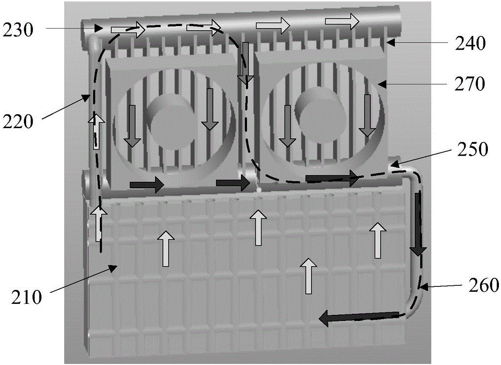
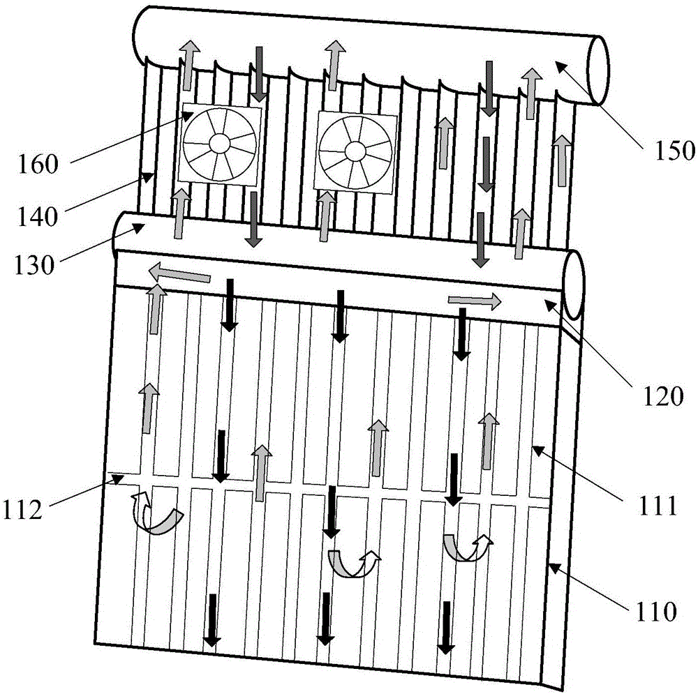
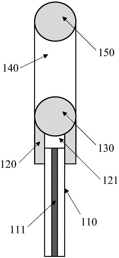
An embodiment of the invention discloses radiating equipment. The weight of the radiating equipment can be lowered and the radiating efficiency of the radiating equipment can be improved. The radiating equipment comprises an evaporator (110), a first-stage pressure balancer (120), a collecting pipe (130), a condenser (140) and a second-stage pressure balancer (150), wherein multiple steam pipelines (111) are arranged in the evaporator (110); working mediums are added in the multiple steam pipelines (111); the upper side of the evaporator (110) is communicated with the lower side of the first-stage pressure balancer (120) through the multiple steam pipelines (111); the upper side of the first-stage pressure balancer (120) is communicated with the lower side of the collecting pipe (130); the upper side of the collecting pipe (130) is communicated with the lower side of the condenser (140); and the upper side of the condenser (140) is communicated with the lower side of the second-stage pressure balancer (150).

Description

technical field [0001] Embodiments of the present invention relate to the field of heat dissipation, and more specifically, to a heat dissipation device. Background technique [0002] In the future 5G technology, hardware devices will be highly integrated, coupled with many requirements such as product miniaturization, high heat flux density and uniform temperature of devices, the existing heat dissipation equipment will not be able to meet the heat dissipation needs of future products. For example, the existing straight-tooth radiators or die-cast straight-tooth radiators are bulky, heavy, difficult to disassemble, and have the disadvantages of uneven heat dissipation and low heat dissipation efficiency. The loop gravity heat pipe (Loop Thermosiphon, LTS) radiator adopts phase change heat dissipation technology, and the heat dissipation performance of the LTS radiator is improved compared with the die-cast radiator, but the volume and weight are still large, and it cannot b...

Claims


Application Information

Patent Timeline
IPC IPC(8): H05K7/20
CPCH05K7/20H05K7/2029
Inventor 刘伟明洪宇平惠晓卫
Owner HUAWEI TECH CO LTD
Learn More