Endoscope

A technology for endoscopes and operating parts, applied in the field of endoscopes, can solve problems such as user fatigue, increased operating force of operating parts, difficult to bend operation, etc., and achieve the effect of reducing operating force and suppressing fatigue

Active Publication Date: 2016-06-15
OLYMPUS CORP
View PDF10 Cites 5 Cited by
  • Summary
  • Abstract
  • Description
  • Claims
  • Application Information

AI Technical Summary

Problems solved by technology

[0005] However, conventional endoscopes such as those disclosed in Japanese Patent Application Laid-Open No. 62-38411 or Japanese Patent Laid-Open No. 2009-89955 are not flexible due to the elastic force of the curved rubber that covers the curved portion provided at the distal end portion of the endoscope. Generating the restoring force that makes the curved part return to a straight line requires the force to elastically deform the curved rubber accompanying the bending of the curved part. In particular, as the bending angle increases, the operating force of the operating member increases as the bending operation is performed.
[0006] For this reason, conventional endoscopes have the problem of causing fatigue to the user or making it difficult to perform delicate bending operations when the bending portion is bent.

Method used


Image

  • Endoscope
  • Endoscope
  • Endoscope

Examples


no. 1 Embodiment approach

[0045] First, a first embodiment of the present invention will be described.

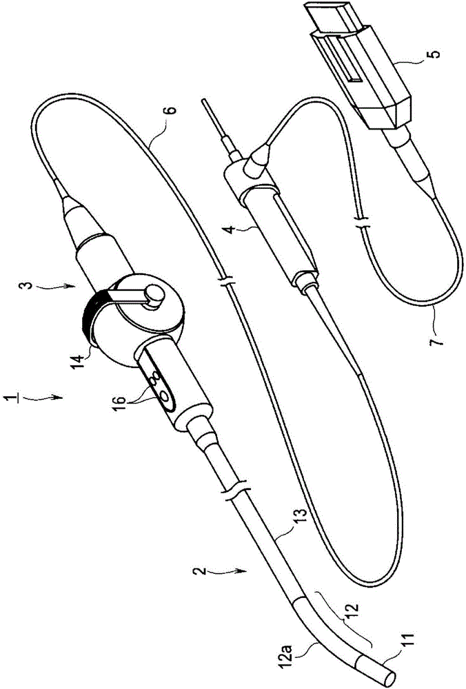
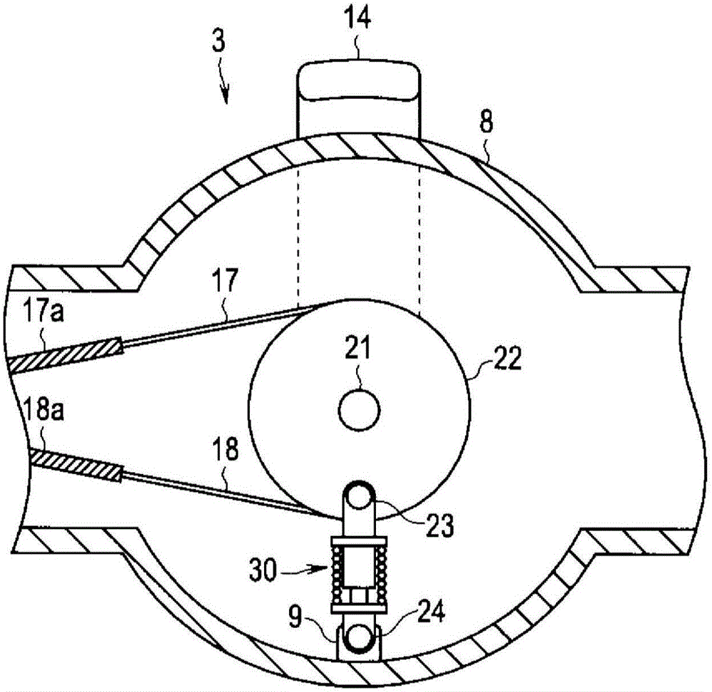
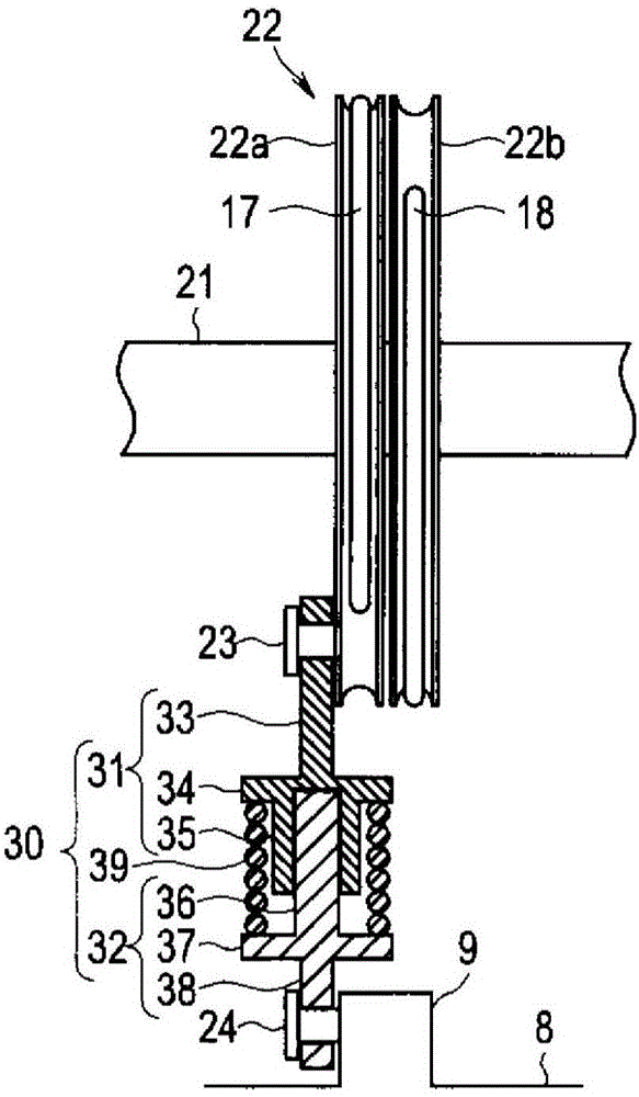
[0046] Figure 1 to Figure 13 Regarding the first embodiment of the present invention, figure 1 is a perspective view showing the overall structure of an endoscope, figure 2 is a cross-sectional view showing the internal structure of the operation unit, image 3 It is a partial cross-sectional view showing the structure of the pulley unit and the operation force reduction part provided in the operation part, Figure 4 It is a figure explaining the action of the operation force reducing part in the state where the bending part is bent toward the upper side, Figure 5It is a figure explaining the function of the operation force reduction part in the state which made the bending part bend toward the lower part side, Image 6 It is a partial sectional view explaining the function of the operation force reduction part in the state where the bending part is bent toward the upper side, Figure 7 It i...

no. 2 Embodiment approach

[0113] Next, a second embodiment of the present invention will be described.

[0114] In addition, in the following description, the same code|symbol is used for the common structural element described in the said 1st Embodiment, and the detailed description of these structural elements is abbreviate|omitted.

[0115] in addition, Figure 14 to Figure 28 Regarding the second embodiment of the present invention, Figure 14 is a plan view showing the structure of an endoscope, Figure 15 is a cross-sectional view showing the internal structure of the operation unit, Figure 16 is a perspective view showing the internal structure of the operation unit, Figure 17 is a cross-sectional view showing the arrangement of tension springs in the operation unit, Figure 18 It is a cross-sectional view showing a tension spring whose one end is hooked to a spring hooking member through which a bending operation wire is inserted, and the other end is hooked to a protrusion of a frame por...


PUM


Abstract

An endoscope (1) is provided with the components of operating wires (17,18,19) which are inserted into an insertion part (2) and an operating part (3) in a through manner and bends a bent part (12) through traction or slack; operating components (14,50) which are arranged on the operating part (3) and performs bending operation on the bent part (12); rotating components (22,53) which are arranged in the operating part (3) and rotate in a linkage manner through operation of the operating components (14,50), thereby performing traction or slack on the operating wires (17,18,19); and an operating force reducing part (30) which applies a rotation torque (M) in the operating direction of the rotating components (22,53) according to operation of the operating components (14,50) for reducing operating force of the operating components (14,50).

Description

technical field [0001] The present invention relates to an endoscope having a bending portion on the distal end side of an insertion portion, and the bending operation of the bending portion is performed by a bending operation member provided on an operating portion on the near side. Background technique [0002] In recent years, endoscopes have been widely used in the medical and industrial fields. In this endoscope, there is such an endoscope that the elongated insertion portion is flexible, and generally, the distal end side of the insertion portion has a bending portion that can bend in a predetermined direction following the user's approaching operation. . [0003] In such an endoscope having a curved portion in the insertion portion, a wide range of inspections can be performed by bending the curved portion to change the observation direction of the observation optical system provided at the distal end portion located at a lower position than the The bent portion is ...

Claims


Application Information

Patent Timeline
Patent Type & Authority Applications(China)
IPC IPC(8): A61B1/00G02B23/24
CPCA61B1/0057G02B23/2476
Inventor 安永浩二关口雄太佐藤优太
Owner OLYMPUS CORP
Why Eureka
Try Eureka