
air nozzle

A technology of air and air flow, applied in air handling equipment, heating/cooling equipment, transportation and packaging, etc.

Active Publication Date: 2018-04-06
DR SCHNEIDER KUNSTWERKE
View PDF12 Cites 0 Cited by
  • Summary
  • Abstract
  • Description
  • Claims
  • Application Information

AI Technical Summary

Problems solved by technology

[0011] A disadvantage of these disclosed prior art is that the known air ejectors have certain geometrical dimensions and dimensions due to the insertion of the vane blocks on the front side

Method used


Image

  • air nozzle
  • air nozzle
  • air nozzle

Examples


Embodiment Construction

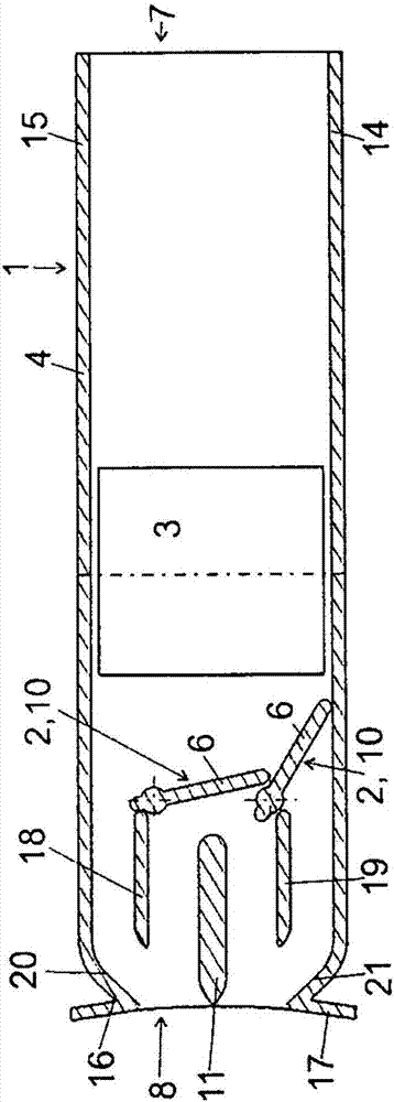
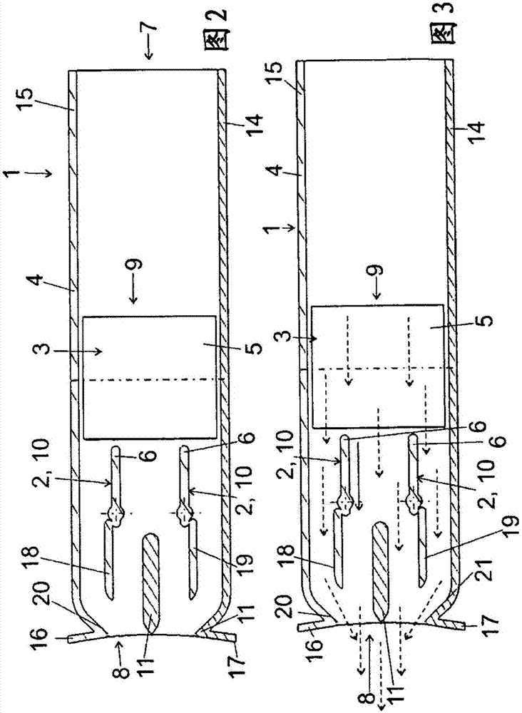
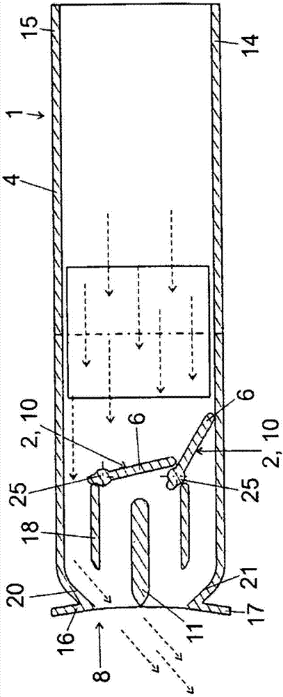
[0043] exist figure 1 The air ejector is shown in a perspective cutaway view. The air ejector 1 comprises a housing 4 having figure 1 A housing side 12 , a housing top 15 and a housing bottom 14 are shown. The housing side 13 of the housing 4 is not shown based on the sectional illustration. The housing 4 has an opening 7 through which an air flow can be supplied and at least one opening 8 for discharging the supplied air flow from the air extractor 1 . Arranged in the housing 4 of the air extractor 1 are the devices 2 , 3 for orienting the air flow entering the air extractor 1 in its course. in accordance with figure 1 The embodiment of the present invention relates to blades 5 , 6 which, in an advantageous embodiment, are combined into a plurality of blade blocks 9 , 10 or respectively into at least one blade block. The individual blades 5 ; 6 of a blade block 9 ; 10 can be deflected individually or collectively in the blade block 9 ; 10 . In the air outlet 8 there ...


PUM


Abstract

An air vent includes a housing, which can be inserted into a wall opening or can be mounted behind a wall opening. An assembly for guiding and / or deflecting and / or stopping the supplied air flow is attached in the housing and comprises two separate louver blocks, which are offset from each other by an angle and / or arranged one behind the other. Each louver block includes a plurality of louvers coupled to each other.

Description

technical field [0001] The invention relates to an air ejector. Background technique [0002] Air ejectors for use in motor vehicles are well known. Such an air extractor has generally separate vane segments arranged at an angle to one another, by means of which the air flow entering the air extractor can be controlled and directed in its course. In this case, the vane piece is arranged in such a way that it delimits the air expeller towards the motor vehicle interior. [0003] DE 10 2004 046 059 discloses an air nozzle, in particular for a motor vehicle ventilation system, the blades of which have at least one adjusting element actuatable by a drive for adjusting the air flow. The adjustment element includes a plurality of vanes. At least one further adjusting element can be actuated by the drive of the adjusting element. [0004] DE 10 2007 061 576 A1 discloses an air nozzle which is provided with at least one swirl-generating guide surface. Furthermore, a baffle is p...

Claims


Application Information

Patent Timeline
Patent Type & Authority Patents(China)
IPC IPC(8): B60H1/34
CPCB60H1/3421
Inventor J·施耐德
Owner DR SCHNEIDER KUNSTWERKE
Learn More