A Passively Controlled Movable Tiplet Device

A passive control, moving blade technology, applied in engine control parameters, wind turbine control, wind turbines that are consistent with the wind direction, etc., can solve problems such as complex system, increased blade quality, and inconvenient maintenance

Active Publication Date: 2022-02-15
LANZHOU UNIVERSITY OF TECHNOLOGY
View PDF0 Cites 0 Cited by
  • Summary
  • Abstract
  • Description
  • Claims
  • Application Information

AI Technical Summary

Problems solved by technology

[0003] Although a rotatable winglet is designed in the prior art, the control method of the designed winglet is active control, and the rotation of the winglet is controlled by the steering gear. The cost of the control method is high, the system is complicated, it is not easy to maintain, and the impairs the quality of the blades, and is not suitable for large-scale wind turbine control

Method used


Image

  • A Passively Controlled Movable Tiplet Device
  • A Passively Controlled Movable Tiplet Device
  • A Passively Controlled Movable Tiplet Device

Examples


Embodiment Construction

[0019] The present invention will be further described below in conjunction with the accompanying drawings.

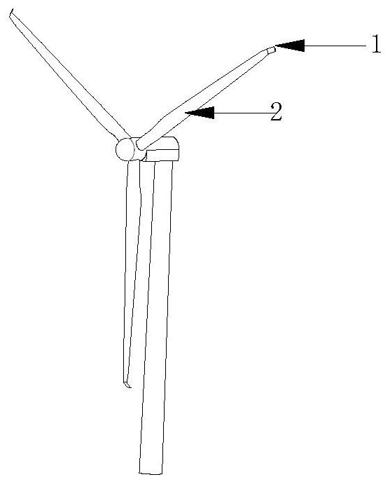
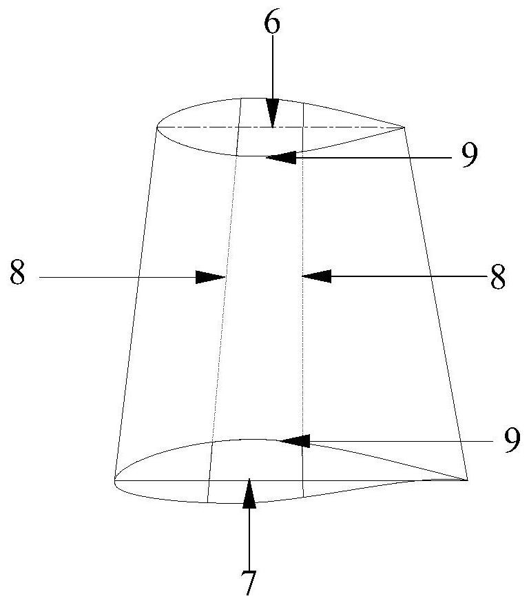
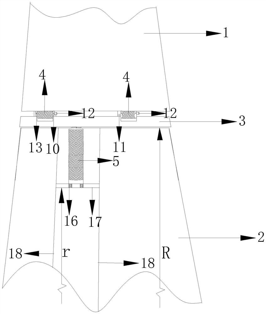
[0020] The present invention consists of winglet 1, blade 2, torsion bracket 3, torsion spring 4, axial spring 5, winglet tip 6, winglet root 7, winglet root web 8, main beam 9, winglet connecting buckle 10, Twist bracket connection buckle 11, torsion shaft 12, winglet locking device 13, axial spring shaft 14, axial spring shaft rotation groove 15, bearing 16, support plate 17, blade web 18, axial spring fixing boss 19 Composition, the specific structure includes blade 2, winglet 1, described winglet 1 is made up of winglet tip 6, winglet root 7, winglet wing root web 8, main beam 9, and described winglet 1 is installed on On the side of the suction surface of the blade 2, an auxiliary mechanism torsion support 3 is provided between the winglet 1 and the blade tip 2, and a torsion spring 4 for controlling the torsion of the winglet 1 is provided between the winglet 1 a...


PUM


Abstract

The present invention is a passively controlled movable tip winglet device, which consists of a blade (2) and a winglet (1). The winglet (1) is installed on one side of the blade (2). ), a torsion bracket (3) is set between the winglet (1) and the torsion bracket (3), and a torsion spring (4) is set between the winglet (1) and the torsion bracket (3). 10) A winglet locking device (13) is installed on the top, a support plate (17) is installed between the two webs of the blade (2), and a bearing (18) is installed at the center of the support plate (17), and the two ends of the axial spring (5) The support plate (17) and the torsion bracket (3) are connected respectively, and the axial spring fixing boss (19) and the axial spring shaft rotation groove (15) are respectively arranged on the axial spring (5). The invention has beneficial effects: reasonable and simple structural design, low manufacturing cost, easy maintenance, capable of protecting blades from interference, wide application range, energy saving and environmental protection.

Description

technical field [0001] The invention relates to the technical field of wind power generation, in particular to a passively controlled movable blade tip small wing device. Background technique [0002] When the wind turbine is running normally, the airflow on the pressure surface near the blade tip will bypass the tip of the blade and flow to the suction surface, generating blade tip vortices, which will reduce the thrust of the blade tip and reduce the output power of the wind turbine. Small wings are added to the tip of the blade to prevent the air flow around the upper and lower surfaces, reduce the induced resistance caused by the tip vortex, reduce the flow around, and increase the pressure difference between the upper and lower surfaces of the blade, so as to increase the thrust and increase the power. output effect. Through numerical simulation, it is found that the fixed winglet has little effect on the power amplification of the wind turbine at low wind speed, but i...

Claims


Application Information

Patent Timeline
Patent Type & Authority Patents(China)
IPC IPC(8): F03D1/06F03D7/02
CPCF03D1/0675F03D7/024F05B2270/32Y02E10/72Y02P70/50
Inventor 杨瑞张浩吴卓琦刘爱瑜郭瑞张康康全佩
Owner LANZHOU UNIVERSITY OF TECHNOLOGY
Why Eureka
Try Eureka