Spray apparatus and method of ejecting mist using spray apparatus

a spray apparatus and spray technology, applied in the direction of spray nozzles, solvent nozzles, manufacturing tools, etc., can solve the problems of unintentional attachment to the components on the board, the reaching distance and ejection angle of the flux solution to be ejected are difficult to make smaller than predetermined values, and the reaching distance becomes long. , to achieve the effect of reducing the amount and flow strength of the mist, reducing the flow rate and ejection pressure of the mis

Inactive Publication Date: 2017-12-28
FUJITSU GENERAL LTD
View PDF3 Cites 0 Cited by
  • Summary
  • Abstract
  • Description
  • Claims
  • Application Information

AI Technical Summary

Benefits of technology

[0012]According to the disclosure, the first nozzle configured to eject the mist is provided with the second nozzle, and a part of the mist ejected from the first nozzle is sucked by the second nozzle. For this reason, a flow rate and an ejection pressure of the mist to be ejected to the ejection target are reduced.
[0013]According to the disclosure, it is possible to reduce the amount and flow strength of the mist to be ejected by the structure simpler than the related art and to spray the flux to a part or a component, for which the spray apparatus of the related art cannot be used.

Problems solved by technology

Therefore, in general, when ejecting the flux by using the spray, it is difficult to make the reaching distance and ejection angle of the flux solution to be ejected smaller than predetermined values.
However, when ejecting and applying the flux to the through-holes of the board by using the spray, the reaching distance becomes long, so that the flux may pass through the through-holes, which are the applying target, and may be unintentionally attached to the components on the board.
Also, the ejection angle becomes large, so that the flux may be unintentionally attached to the mounted components, which are not the applying target.
In this case, in a rotary encoder to be used for a dial for volume adjustment of an audio product, for example, the flux may be introduced into a component, so that a malfunction may be caused.
However, the corresponding apparatus has a complicated structure and is expensive.
However, with the flux applying apparatus disclosed in Patent Document 1, it is not possible to control an attachment amount of the flux into the through-holes and the flux is attached beyond necessity.
Also, when drying and removing the surplus flux accumulated in the through-holes, it takes time until the drying is completed, which may lower the productivity.
Also, the flux applying apparatus has demerits that a structure thereof is complex and a failure risk is high.

Method used


Image

  • Spray apparatus and method of ejecting mist using spray apparatus
  • Spray apparatus and method of ejecting mist using spray apparatus
  • Spray apparatus and method of ejecting mist using spray apparatus

Examples


embodiments

[0084]In the below, a comparison test of an embodiment of the flux spray apparatus of the first illustrative embodiment and a conventional example is described. However, the disclosure is not limited to the below embodiment.

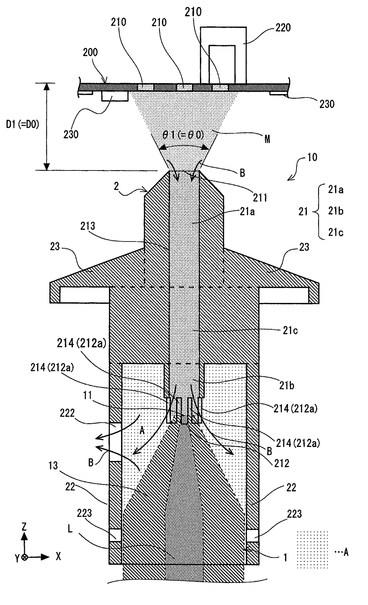
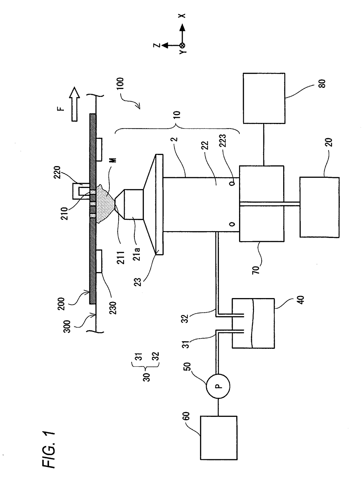
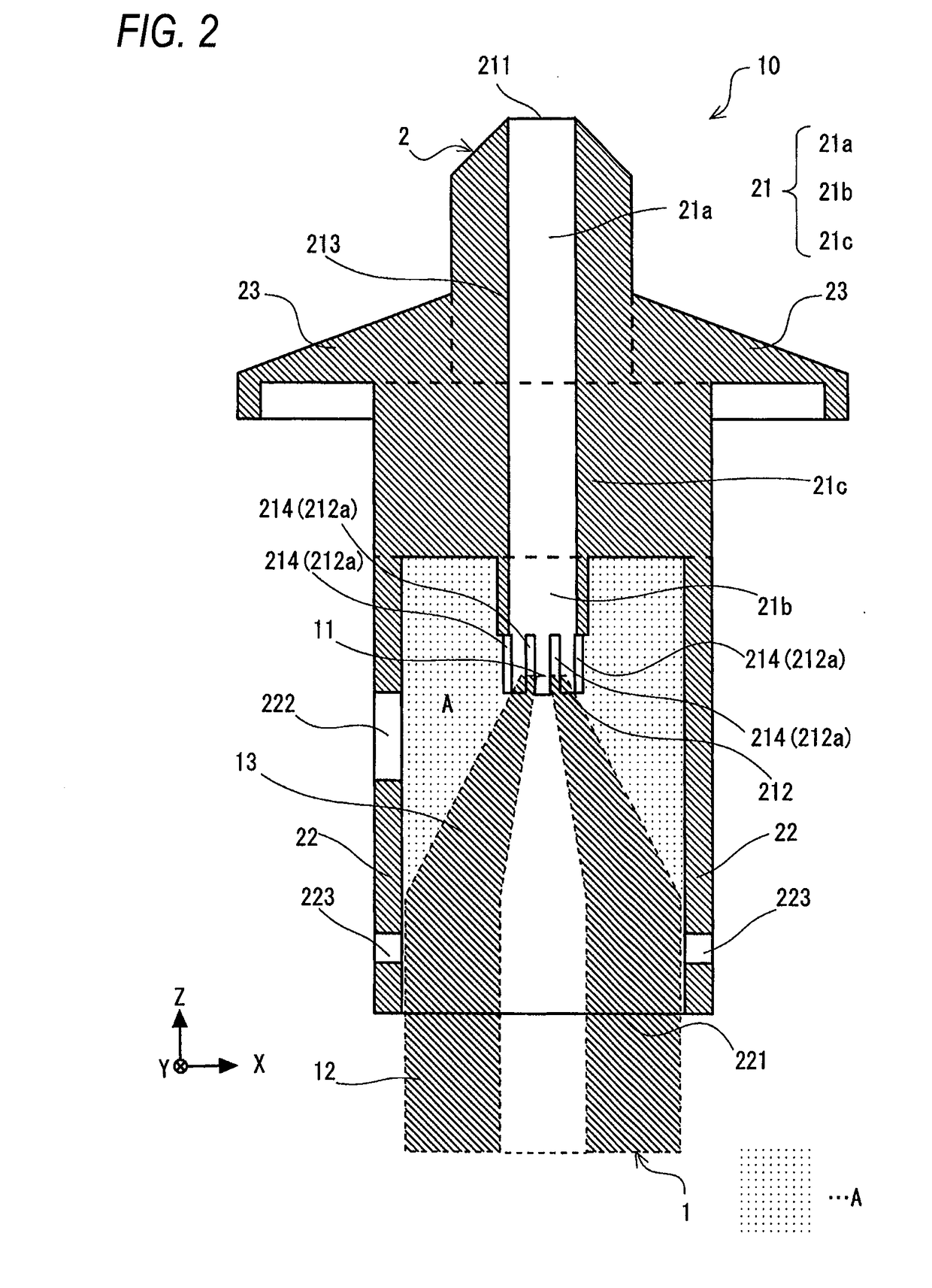
[0085]A flux spray apparatus of the embodiment corresponds to the flux spray apparatus 100 of the first illustrative embodiment. That is, a nozzle device of the embodiment has a second nozzle corresponding to the second nozzle 2 mounted to a first nozzle corresponding to the first nozzle 1 and is configured to suck a part of a flux ejected from the first nozzle by applying a negative pressure.

[0086]A flux spray apparatus of the conventional example corresponds to the flux spray apparatus 100a of the related art. That is, the flux spray apparatus is an apparatus where the second nozzle is detached from the flux spray apparatus of the embodiment.

[0087]In the comparison test, the flux reaching distances in the embodiment and the conventional example are compared. In...


PUM

PropertyMeasurementUnit
inner diameteraaaaaaaaaa
negative pressureaaaaaaaaaa

Abstract

There is provided a spray apparatus. A first nozzle is configured to eject mist. A second nozzle is provided around the first nozzle. The second nozzle is configured to suck a part of the mist ejected from the first nozzle and to eject a remnant of the mist to an ejection target.

Description

CROSS-REFERENCE TO RELATED APPLICATIONS[0001]This application is based on and claims priority from Japanese Patent Application No. 2016-125009 filed on Jun. 23, 2016.TECHNICAL FIELD[0002]The disclosure relates to a spray apparatus and a method of ejecting mist by using the spray apparatus.RELATED ART[0003]In the related art, a soldering has been widely used as a method of bonding metal components such as lands and through-holes formed on a surface of a printed board and lead lines of mounted components such as a semiconductor device and a capacitor mounted on the board so that energization can be enabled. As a pre-process of the soldering, it is necessary to apply a flux solution. In general, the flux solution is a liquid in which a rosin-based or acryl-based resin, an alcohol or aromatic solvent and an activator are mixed. The flux solution is uniformly applied to places in advance, at which the metal components and the mounted components are to be bonded by the soldering, on the p...

Claims


Application Information

Patent Timeline
Patent Type & Authority Applications(United States)
IPC IPC(8): B23K3/08B05B1/28
CPCB05B1/28B23K3/082B23K1/203B05B15/531H01L21/00
Inventor HAYASHI, HISAKIWATANABE, YASUYUKI
Owner FUJITSU GENERAL LTD
Why Eureka
Try Eureka