Eureka AIR delivers breakthrough ideas for toughest innovation challenges, trusted by R&D personnel around the world.

Wall-hung air conditioner with drainage structure

An air conditioner and wall-mounted technology, which is applied in the field of wall-mounted air conditioners with a drainage structure, can solve the problems of insufficient wind output and low air supply volume, and achieve increased air supply volume, large air intake volume, and faster flow Effects of Speed ​​and Uniformity

Inactive Publication Date: 2016-06-22
QINGDAO HAIER AIR CONDITIONER GENERAL CORP LTD
View PDF4 Cites 13 Cited by
  • Summary
  • Abstract
  • Description
  • Claims
  • Application Information

AI Technical Summary

Problems solved by technology

[0003] The purpose of the present invention is to provide a wall-mounted air conditioner with a drainage structure to solve the problems of the existing wall-mounted air conditioners that the air output is not soft enough and the air supply volume is small

Method used


Image

  • Wall-hung air conditioner with drainage structure
  • Wall-hung air conditioner with drainage structure
  • Wall-hung air conditioner with drainage structure

Examples


Embodiment Construction

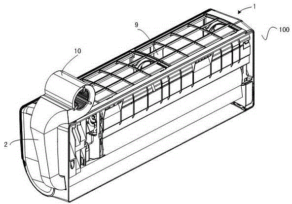
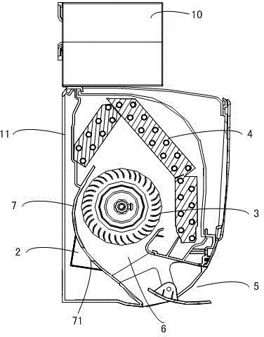
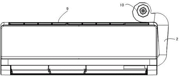
[0027] In order to make the object, technical solution and advantages of the present invention clearer, the present invention will be further described in detail below in conjunction with the accompanying drawings and embodiments.

[0028] See Figure 1 to Figure 5 An embodiment of the present invention shown is specifically an embodiment of the indoor unit of the wall-mounted air conditioner with a drainage structure of the present invention.

[0029] in, figure 1 is a perspective view of the indoor unit of this embodiment; figure 2 yes figure 1 Schematic diagram of the internal structure; image 3 yes figure 1 main view of Figure 4 and Figure 5 They are the front view and perspective view of the drainage structure in this embodiment, respectively.

[0030] combine Figure 1 to Figure 5 As shown, the indoor unit 100 of the wall-mounted air conditioner in this embodiment includes a casing 1, and a cross-flow fan 3 and a heat exchanger 4 are arranged in the casing, a...


PUM


Abstract

The invention discloses a wall-hung air conditioner with drainage structure. The wall-hung air conditioner comprises an indoor unit; the indoor unit includes a shell; a cross flow fan and a heat exchanger are formed in the shell; a strip-shaped air outlet is formed in the shell; an air guide port is formed in a back volute, provided with an air supply flue of the main cross flow fan, along the length direction of the air outlet; and an induced draft fan is arranged above the shell, and is communicated with the air guide port through an air guide channel. The wall-hung air conditioner can solve the problems of insufficient softness of exhaust and low air supply quantity in a traditional wall-hung air conditioner.

Description

technical field [0001] The invention belongs to the technical field of air conditioning, in particular relates to a wall-mounted air conditioner, and more specifically relates to a wall-mounted air conditioner with a drainage structure. Background technique [0002] The air supply process of the indoor unit of the existing split-type wall-mounted air conditioner is as follows: the air in the room, as non-heat exchange air, enters the indoor unit under the action of the cross-flow fan, and forms heat exchange air after heat exchange by the heat exchanger. , the heat exchange air is blown out from the air outlet under the action of the cross-flow fan. Thus, all the air blown from the air outlet is heat exchange air. The air sent by this air supply method is all the air after heat exchange by the heat exchanger. Compared with the indoor air, the temperature difference is relatively large, so that the air is not soft enough, and it feels uncomfortable to blow directly on the us...

Claims


Application Information

Patent Timeline
Patent Type & Authority Applications(China)
IPC IPC(8): F24F1/00F24F13/06
Inventor 王永涛闫宝升李健关婷婷
Owner QINGDAO HAIER AIR CONDITIONER GENERAL CORP LTD
Why Eureka
Eureka Blog
Learn More