
Curvature fairing method for high-speed numerical control processing track

A technology for processing trajectory and curvature, applied in the direction of digital control, program control, electrical program control, etc., can solve the problems of affecting feed speed, curvature fluctuation, and reducing processing efficiency

Inactive Publication Date: 2016-06-22
SHANGHAI JIAO TONG UNIV
View PDF6 Cites 24 Cited by
  • Summary
  • Abstract
  • Description
  • Claims
  • Application Information

AI Technical Summary

Problems solved by technology

[0004] If the curvature of the helical milling tool rail fluctuates at the corner, it will still affect the feed speed during the machining process and reduce the machining efficiency

Method used


Image

  • Curvature fairing method for high-speed numerical control processing track
  • Curvature fairing method for high-speed numerical control processing track
  • Curvature fairing method for high-speed numerical control processing track

Examples


Embodiment Construction

[0047] The present invention will be described in detail below in conjunction with specific embodiments. The following examples will help those skilled in the art to further understand the present invention, but do not limit the present invention in any form. It should be noted that those skilled in the art can make several modifications and improvements without departing from the concept of the present invention. These all belong to the protection scope of the present invention.

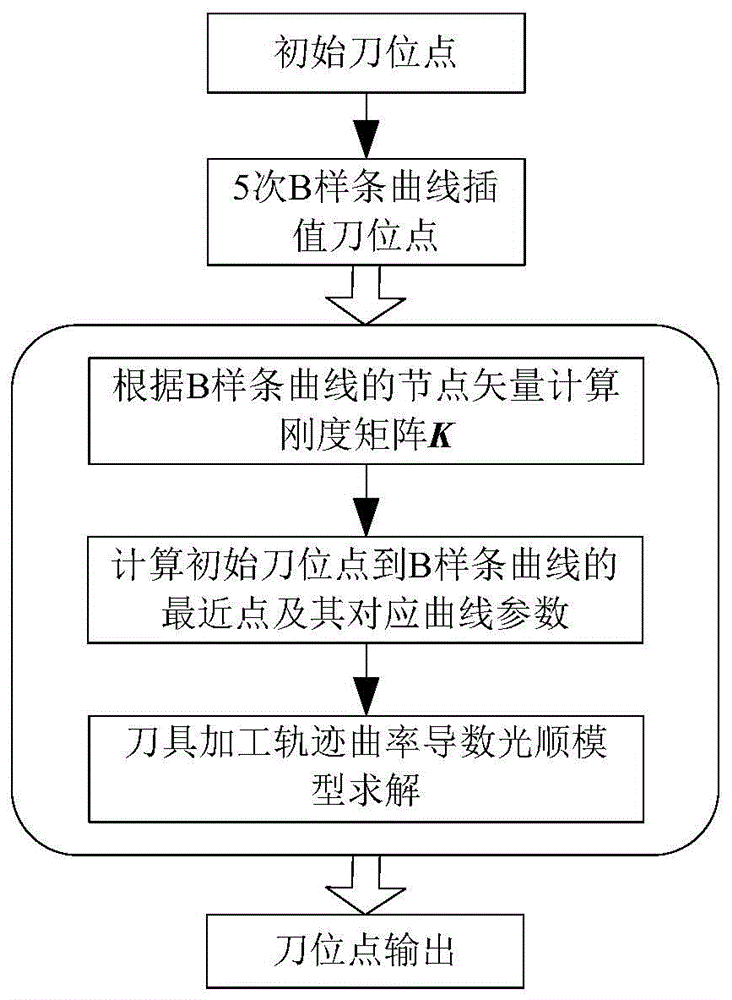
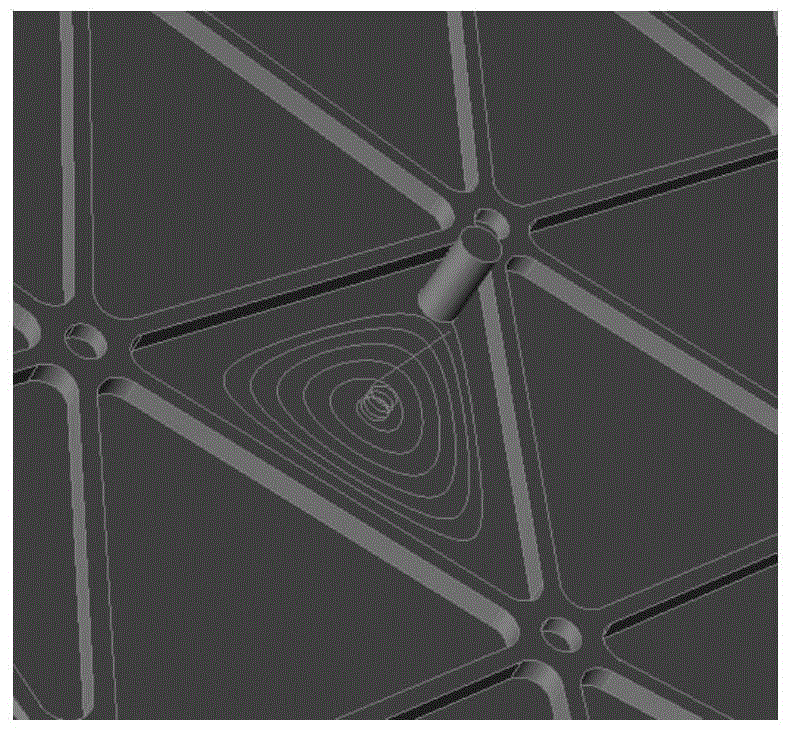
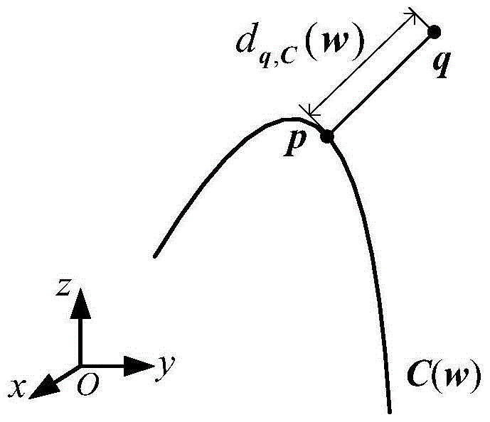
[0048] In this example, if figure 1 , figure 2 , image 3 as well as Figure 4 As shown, the present invention uses the distance function from the point to the curve to calculate the fitting error, measures the smoothness of the tool machining trajectory by the sum of the squares of the curvature derivatives of the curve, and establishes a curvature smoothness optimization model of the high-speed CNC machining trajectory.

[0049] Using B-spline curve of degree 5 to express tool machining traj...


PUM


Abstract

The invention provides a curvature fairing method for a high-speed numerical control processing track. The curvature fairing method comprises the steps of: inputting tool location points of an initial processing track; interpolating the initial tool location points by utilizing B-spline curve repeatedly to obtain a tool processing track line, and representing the tool processing track line by using the B-spline curve; calculating a stiffness matrix of a track curve according to node vectors of the B-spline curve; calculating a closest point from each initial tool location point to the B-spline curve and curve parameters corresponding to the closet points, and calculating a first-order derivative of a distance (from the initial tool location points to the closest points of the B-spline curve) to control points of the B-spline curve; solving a tool processing track curvature derivative fairing model by adopting a sequence linear method to obtain a processing track after fairing optimization; and outputting tool locating points of the tool processing track after fairing optimization. The curvature fairing method solves the problem of generating the high-speed numerical control processing tool track with fair curvature, and is suitable for generating a 2.5-axis cavity high-speed processing track.

Description

technical field [0001] The invention relates to the generation of a smooth 2.5-axis cavity milling tool machining track, in particular to a curvature smoothing method of a high-speed numerical control machining track. Background technique [0002] In the integral panel processing of aerospace, a large number of triangular and quadrilateral cavities need to be processed. High-speed cutting is an effective means to realize high-efficiency machining of integral wall panels. [0003] The method of ring cutting or line cutting, and the method of direct transition or arc transition at the corner will make the machine tool frequently accelerate and decelerate during the machining process, resulting in vibration of the machine tool, and it is difficult to improve the machining efficiency. The helical milling tool path can effectively reduce the fluctuation of tool load and tool wear, and can improve the processing efficiency and quality. [0004] If the curvature of the helical mi...

Claims


Application Information

Patent Timeline
IPC IPC(8): G05B19/19
CPCG05B19/19G05B2219/36363
Inventor 毕庆贞卢耀安陈化朱利民丁汉
Owner SHANGHAI JIAO TONG UNIV
Learn More