Contact net pantograph stagger value overrun defect recognition method and system

A technology for pulling overruns and defect identification, applied in the catenary field, to achieve the effect of reducing false alarms, reducing false alarms, and improving identification accuracy

Active Publication Date: 2016-06-29
CHENGDU NAT RAILWAYS ELECTRICAL EQUIP
View PDF3 Cites 10 Cited by
  • Summary
  • Abstract
  • Description
  • Claims
  • Application Information

AI Technical Summary

Problems solved by technology

[0006] The purpose of the present invention is to overcome the deficiencies of the prior art, aiming at the inconvenience of manual on-board patrol to check the abnormal information of the catenary, a method and system for identifying the over-limit defect of the

Method used


Image

  • Contact net pantograph stagger value overrun defect recognition method and system
  • Contact net pantograph stagger value overrun defect recognition method and system
  • Contact net pantograph stagger value overrun defect recognition method and system

Examples


Example Embodiment

[0054] The technical solutions of the present invention are further described in detail below with reference to the accompanying drawings, but the protection scope of the present invention is not limited to the following.

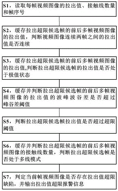
[0055] Due to the relatively complex advantages of the external environment, the pull-out value is sometimes miscalculated, and the pull-out value cannot be judged only by the pull-out value. Therefore, the present invention introduces limited conditions such as peak-valley difference threshold, extreme value, number of contact lines, etc., to limit the pull-out over-limit judgment, and reduce the problem of false alarms of pull-out value over-limit defects.

[0056] (1) Defect identification method for over-limit defect of catenary pantograph pull-out value

[0057] like figure 1 As shown, this embodiment describes a method for identifying a defect of a catenary pantograph pull-out value exceeding the limit, and the method includes at least the following ...


PUM


Abstract

The invention discloses a contact net pantograph stagger value overrun defect recognition method and system.The method comprises the steps that an image processing technology is adopted to calculate a stagger value of pantograph, condition limiting is conducted on stagger value overrun judgment according to factors such as stagger value smoothness, whether in an extreme value state or not and a contact line mode, and alarm interference is removed.According to the contact net pantograph stagger value overrun defect recognition method and system, the problem of misinformation of a stagger value overrun defect is effectively solved, stagger value overrun judgment can be accurately conducted, and the pantograph abnormal condition checking method is efficient, convenient and rapid.

Description

technical field [0001] The invention relates to the field of catenary, in particular to a method and system for identifying a defect that a pantograph pull-out value of a catenary exceeds the limit. Background technique [0002] The catenary is a high-voltage transmission line erected in a "zigzag" shape along the sky above the rails in the electrified railway for pantographs to take current. The catenary is the main frame of the railway electrification project, and it is a special form of transmission line erected along the railway line to supply power to the rail vehicles. Generally, it is composed of contact suspension, support device, positioning device, pillar and foundation. [0003] The development of electrified railway is an inevitable trend of railway modernization. All electrified railways use electric traction, and electric locomotives must reliably obtain electric energy from catenary under high-speed operating conditions, otherwise it will affect the performa...

Claims


Application Information

Patent Timeline
IPC IPC(8): G06K9/00
CPCG06V20/41
Inventor 范国海周吉李立峰胡蓉
Owner CHENGDU NAT RAILWAYS ELECTRICAL EQUIP
Why Eureka
Try Eureka