Laser-Integrated Head Gimbal Assembly Having Laser Contact Protection

A technology of lasers and magnetic heads, applied in the protection measures of magnetic heads, instruments, magnetic recording, etc.

Inactive Publication Date: 2016-06-29
HITACHI GLOBAL STORAGE TECH NETHERLANDS BV
View PDF6 Cites 2 Cited by
  • Summary
  • Abstract
  • Description
  • Claims
  • Application Information

AI Technical Summary

Problems solved by technology

The limited mechanical clearances associated with ...

Method used


Image

  • Laser-Integrated Head Gimbal Assembly Having Laser Contact Protection
  • Laser-Integrated Head Gimbal Assembly Having Laser Contact Protection
  • Laser-Integrated Head Gimbal Assembly Having Laser Contact Protection

Examples


Embodiment Construction

[0019] A method is described for a heat assisted magnetic recording (HAMR) head gimbal assembly (HGA) that protects the associated HAMR heating source from unwanted contact. In the ensuing description, for purposes of explanation, numerous specific details are set forth in order to provide a thorough understanding of the embodiments of the invention described herein. It will be apparent, however, that the embodiments of the invention described herein may be practiced without these specific details. In other instances, well-known structures and devices are shown in block diagram form in order not to unnecessarily obscure the embodiments of the inventions described herein.

[0020] Physical Description of Exemplary Operating Environment

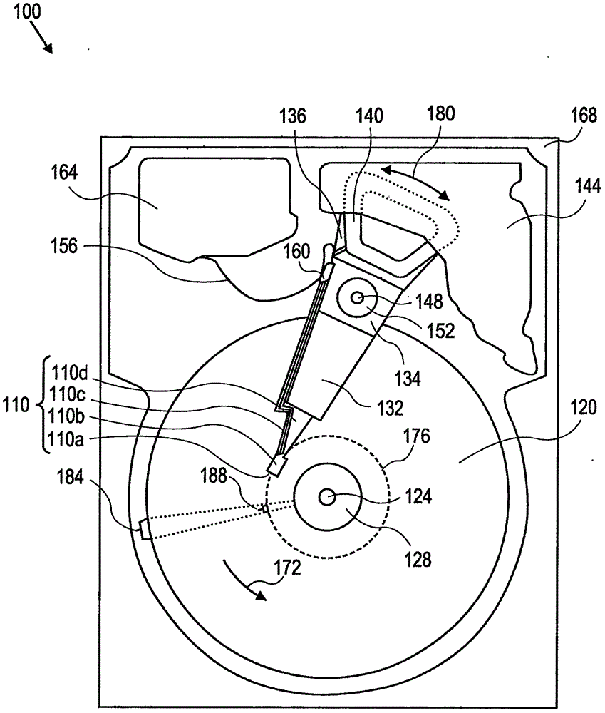
[0021] Embodiments of the present invention may be used in the context of HAMRHGA in hard disk drive (HDD) storage devices. Therefore, according to an embodiment of the present invention, in figure 1 A plan view depicting HDD 100 is shown in...


PUM


Abstract

A heat-assisted magnetic recording (HAMR) head gimbal assembly (HGA) protects the associated HAMR heating source from unwanted contact, such as from contact with an adjacent HAMR laser in response to a shock event. The HGA is configured such that the distance between the flexure and the top of a load beam flange is greater than the height of a submount associated with the heating source, and the height of the submount may also be greater than the height of the heating source, thus protecting against contact between adjacent heating sources.

Description

technical field [0001] Embodiments of the present invention relate generally to hard disk drives, and more particularly to laser-integrated head gimbal assemblies (HeadGimbalAssembly, HGA). Background technique [0002] A Hard Disk Drive (HDD) is a non-volatile storage device that is housed within a protected enclosure and stores digitally encoded data on one or more platters with magnetic surfaces. When the hard disk is in operation, each magnetic recording disk is spun rapidly by the spindle system. Data is read from or written to a magnetic recording disk using a read / write head, which is placed at a specific location on the disk by an actuator. The read / write head uses a magnetic field to read or write data from or to the surface of the magnetic recording disk. The write head utilizes an electric current flowing through a coil, which creates a magnetic field. Electrical pulses with different positive and negative current patterns are sent to the write head. Current i...

Claims


Application Information

Patent Timeline
IPC IPC(8): G11B5/48
CPCG11B5/4806G11B5/488G11B5/40G11B5/4833G11B2005/0021G11B5/4826G11B13/04
Inventor 难波入三中村滋男铃木健治松本拓也宫本治一
Owner HITACHI GLOBAL STORAGE TECH NETHERLANDS BV
Why Eureka
Try Eureka