Anti-fall anti-return and anti-overflow structure and inspection well and method

An anti-flooding and anti-falling technology, which is applied to underwater structures, infrastructure engineering, drainage structures, etc., can solve the problem of being transferred into the well, being washed away by water, not being able to solve water leakage, and short-term heavy rainfall and other problems, to achieve the effect of convenient fixing and easy taking of the large cover

Active Publication Date: 2016-07-06
SHANDONG TONGYUAN DESIGN GRP
View PDF4 Cites 2 Cited by
  • Summary
  • Abstract
  • Description
  • Claims
  • Application Information

AI Technical Summary

Problems solved by technology

[0004] First, the short-term rainfall is heavy, and the capacity of drainage pipes is insufficient
[0005] Second, the large amount of water leaks from the pipe network, causing a large amount of water on urban roads
[0006] In particular, the second reason is more harmful. Once the pipe network leaks, the manhole cover of the inspection well is jacked up, and passers-by cannot see the situation under their feet. Sometimes they are transferred into the well and are washed away by water. There are few structures that can prevent people or objects from falling from the wellhead of the inspection well at the same time. Even if there are, most of them are devices for preventing the manhole cover from falling into the well, and this structure can not solve the problem of water leakage.

Method used


Image

  • Anti-fall anti-return and anti-overflow structure and inspection well and method
  • Anti-fall anti-return and anti-overflow structure and inspection well and method
  • Anti-fall anti-return and anti-overflow structure and inspection well and method

Examples


Embodiment 2

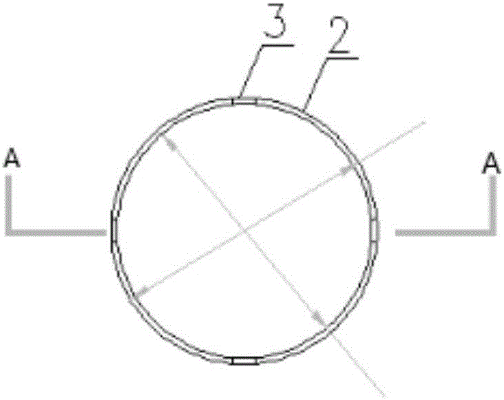
[0060] The difference between this embodiment and Embodiment 1 is that the well circle includes at least two sections of support frames arranged along the wellhead wall, and the derrick is a cross plate or a hollowed-out support plate, and the derrick is also installed by rotating the method. Very convenient.

[0061] A method for installing an anti-fall and anti-backflow structure, the specific steps are as follows:

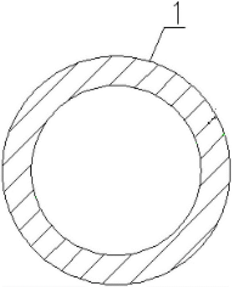
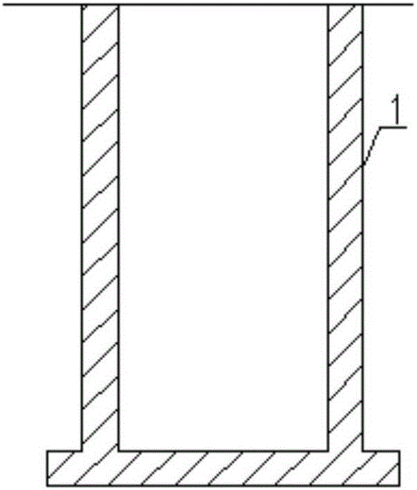
[0062] 1) Set at least two sections of support frames for supporting the derrick on the wellhead wall of the inspection well 1;

[0063] 2) Install the derrick through the support frame;

[0064] 3) Set the boom passing through the derrick, pass through the large cover plate and the small cover plate in sequence at the lower end of the boom, and set the supporting device to support the small cover plate.

[0065] A method for disassembling an anti-fall and anti-backflow structure, the specific steps are as follows:

[0066] 1) After removing the well cover, t...

Embodiment 3

[0069] The difference between this embodiment and Embodiment 1 is: there is an opening in the middle of the large cover for easy access to the large cover; In the opening of the cover plate, correspondingly, the size of the opening increases gradually, and the thickness of the small cover plate is greater than that of the large cover plate, so as to block the opening of the large cover plate. At the same time, when entering the inspection well, push the small cover plate open , take out the large cover through the opening.


PUM


Abstract

The invention discloses an anti-fall anti-return and anti-overflow structure and an inspection well and method. The structure comprises a derrick arranged on the wellhead wall of the inspection well in a manner of being parallel to a well lid, wherein the derrick is fixed through a well loop fixed on the wellhead wall; a large cover plate is arranged below the derrick; an opening through which the large cover plate is conveniently fetched is formed in the middle of the large cover plate; a small cover plate is arranged at the lower part of the large cover plate; the derrick, the large cover plate and the small cover plate are connected through connecting structures. Due to the arrangement of the well loop, the large cover plate and the small cover plate are prevented from continuously moving upwards, continuous rise of rainwater is prevented, and due to the arrangement of the well loop, the derrick and the large cover plate, pedestrians are prevented from accidentally dropping from the wellhead on a rainy day; moreover, due to the well loop taking an approximately C shape, the derrick can be effectively fixed, drop of the well lid or other people or objects can be avoided with the cooperation of the large cover plate and the small cover plate, and the two cover plates are effectively prevented from continuously moving upwards.

Description

technical field [0001] The invention relates to a rainwater inspection well, in particular to an anti-falling and anti-backflow structure, an inspection well structure and a method. Background technique [0002] At present, the phenomenon of urban waterlogging is very prominent in major cities across the country. Under this background, the state has also introduced relevant policies such as sponge city construction. [0003] Through the research on the causes of urban waterlogging, it is found that there are two main causes of waterlogging: [0004] First, the short-term rainfall is heavy, and the capacity of drainage pipes is insufficient. [0005] Second, the large amount of water leaks from the pipe network, causing a large amount of water to accumulate on urban roads. [0006] In particular, the second reason is more harmful. Once the pipe network leaks, the manhole cover of the inspection well is jacked up, and passers-by cannot see the situation under their feet. Som...

Claims


Application Information

Patent Timeline
Patent Type & Authority Applications(China)
IPC IPC(8): E03F5/02E03F5/042E02D29/12E02D29/14
CPCE02D29/127E02D29/14E03F5/02E03F5/042
Inventor 羡巨智周艳
Owner SHANDONG TONGYUAN DESIGN GRP
Why Eureka
Try Eureka