
A cartridge integrated valve group and its working method

A valve group and plug-in technology, which is applied in the field of valve groups, can solve the problems of affecting the actual diameter, large leakage possibility, and many sealing points, so as to reduce the possibility of leakage, flexible flow channel design, and reduce sealing points. Effect

Inactive Publication Date: 2018-07-20
JIANDE XINANJIANG PNEUMATIC COMPONENT CO LTD
View PDF7 Cites 0 Cited by
  • Summary
  • Abstract
  • Description
  • Claims
  • Application Information

AI Technical Summary

Problems solved by technology

The sealing cone surface between the upper and lower ports of the valve fits and seals the valve core. When the valve is closed, the valve stem has an upward pull on the valve core. When the valve is opened, the valve stem has a downward thrust on the valve core. The tightness of the valve core The nut is subject to variable load for a long time and is easy to loosen
At the same time, when the valve is opened or closed, the valve stem remains in the upper and lower flow ports, which affects the actual diameter and thus the flow capacity of the valve.
[0004] Moreover, the sealing surface of the existing cut-off valve is at the lower port, so that when the actuator is removed, the actuator and the valve core cannot be directly removed. It is necessary to remove the lower cover first, unscrew the valve core fastening screw, and remove the valve core to remove the actuator. The device is removed from the valve body, which will make the replacement and maintenance of the valve more troublesome. At the same time, the valve and the pipeline are connected in the form of flange or pipe thread, and the connection between the pipeline and the pipeline is in the form of welding. This form of The pipeline occupies a large space, the flow channel is long, there are many welding points, many sealing points, and the possibility of leakage is large

Method used


Image

  • A cartridge integrated valve group and its working method
  • A cartridge integrated valve group and its working method
  • A cartridge integrated valve group and its working method

Examples


Embodiment Construction

[0042] The present invention will be described in further detail below in conjunction with the accompanying drawings, but it is not intended to limit the protection scope of the present invention.

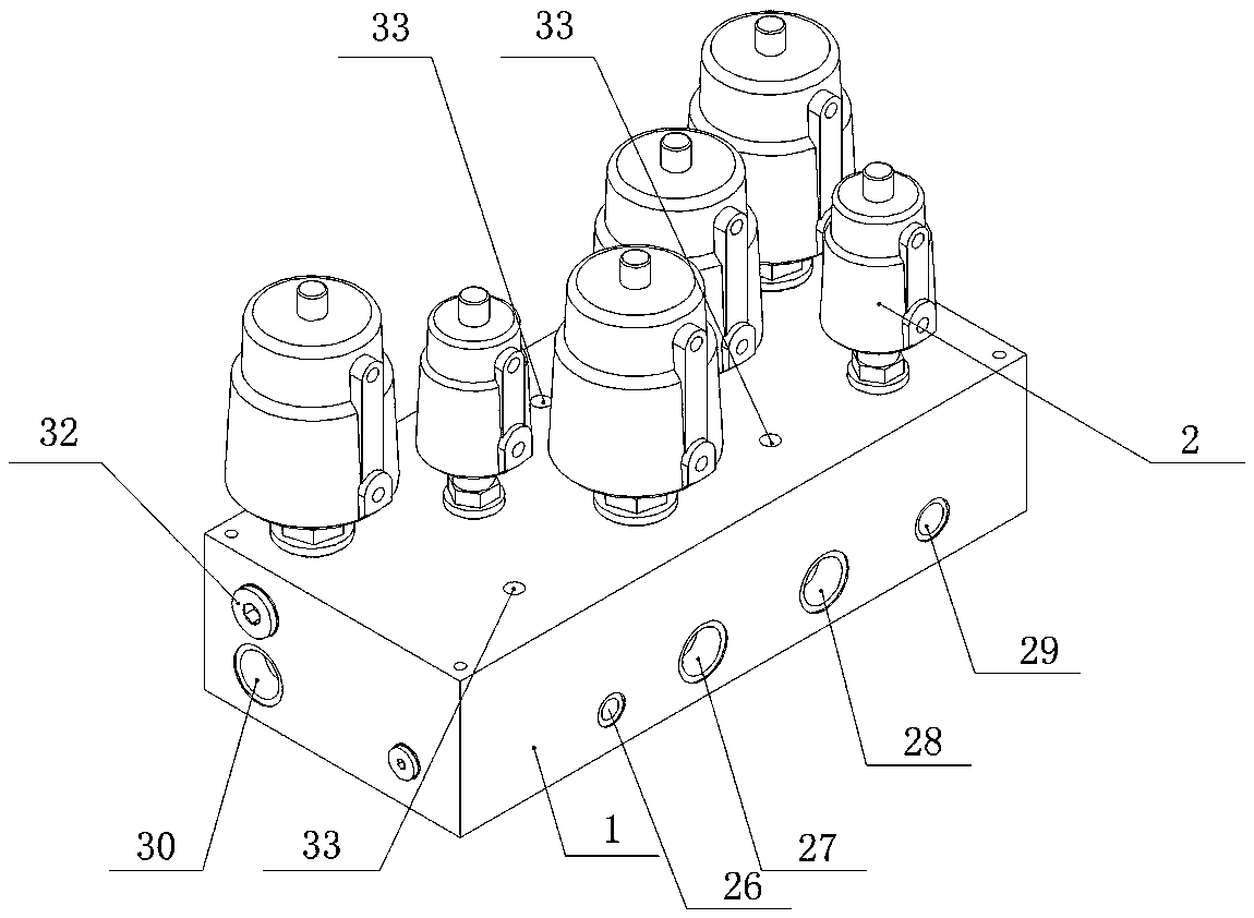
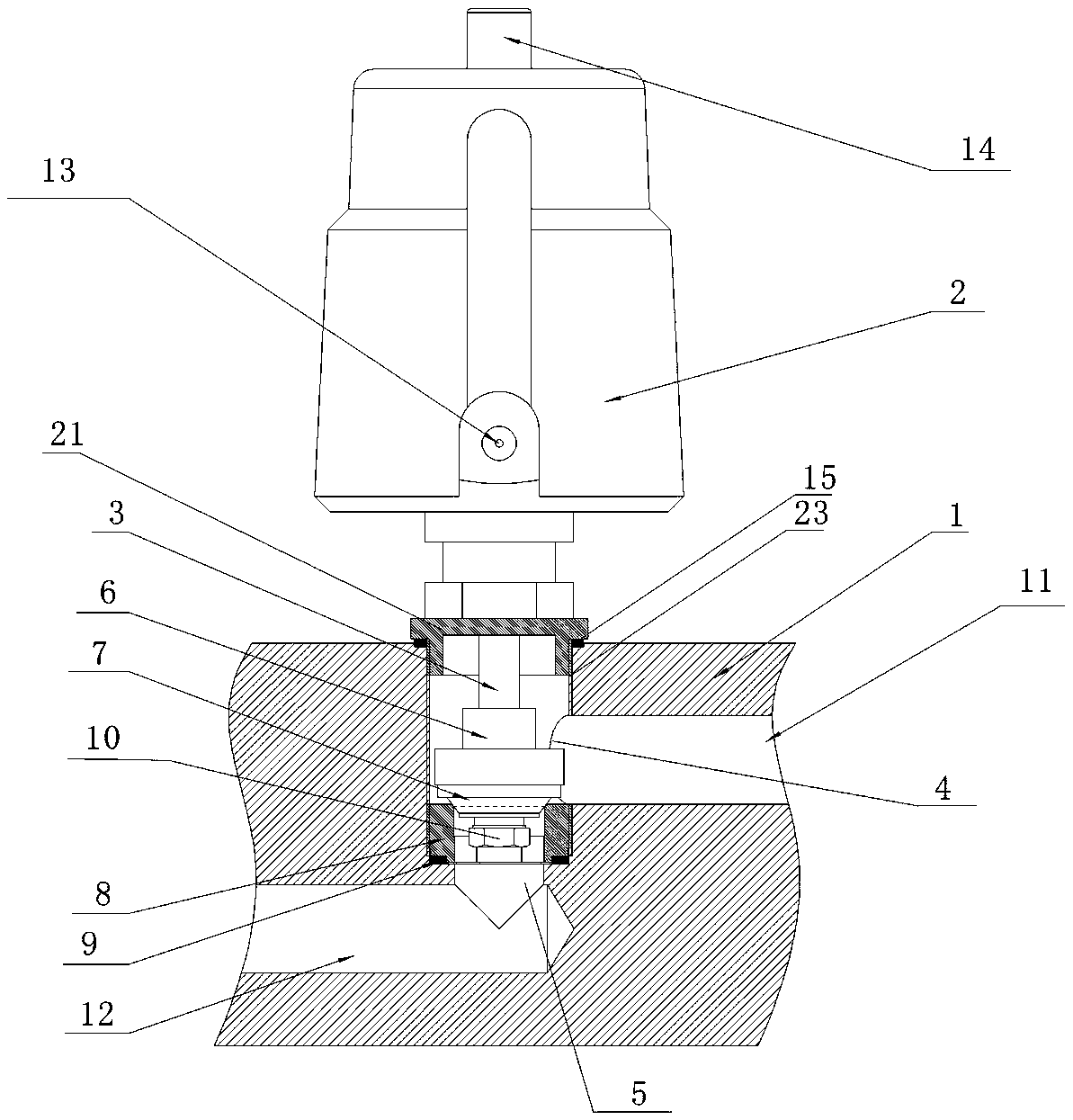
[0043] Such as Figure 2-8As shown, a plug-in integrated valve group includes a valve block 1 and six valves installed on the valve block 1. The valve block 1 is provided with 4 medium inlets and 4 medium inflow channels 12 matching the medium inlets. , and 2 medium outlets and 2 medium outflow channels 11 matching the medium outlets, each medium inlet is connected to the corresponding valve through the corresponding medium inflow channel 12, and the valve corresponding to the medium is connected to the outlet through the medium outflow channel The inlet of the controlled valve is connected to the E outlet 30 or the F outlet 31 through the outlet valve. The valve includes a valve block 1, a valve actuator 2, a valve stem 3, a valve upper port 4, a valve lower port 5, a valve seali...


PUM


Abstract

The invention discloses a plug-in mounting type integration valve set. The plug-in mounting type integration valve set comprises a valve block and a plurality of valves, the valve block is provided with a plurality of medium inlets, a plurality of medium flowing-in runners, a plurality of medium outlets and a plurality of medium flowing-out runners; each medium inlet is connected with the corresponding valve through the corresponding medium flowing-in runner, and all valves are connected with the corresponding medium outlets through the corresponding medium flowing-out runners; and each valve comprises a valve executor, a valve rod, an upper valve opening, a lower valve opening, a valve sealing disc and a valve sealing holder, wherein each valve sealing holder is located between the corresponding upper valve opening and the corresponding lower valve opening, a V-shaped sealing head is arranged at the bottom of each valve sealing disc, an arc-shaped chamfer is arranged at the top of each valve sealing holder, and valve connecting bases are arranged at the top of the valve block. According to the plug-in mounting type integration valve set, the multiple medium flowing-in runners can be controlled to be on or off to conduct confluence; the sealing effect is good when the valves are closed, and the flow capacity is high when the valves are opened; and meanwhile, sealing points for pipe connection are fewer, and the leakage possibility is reduced.

Description

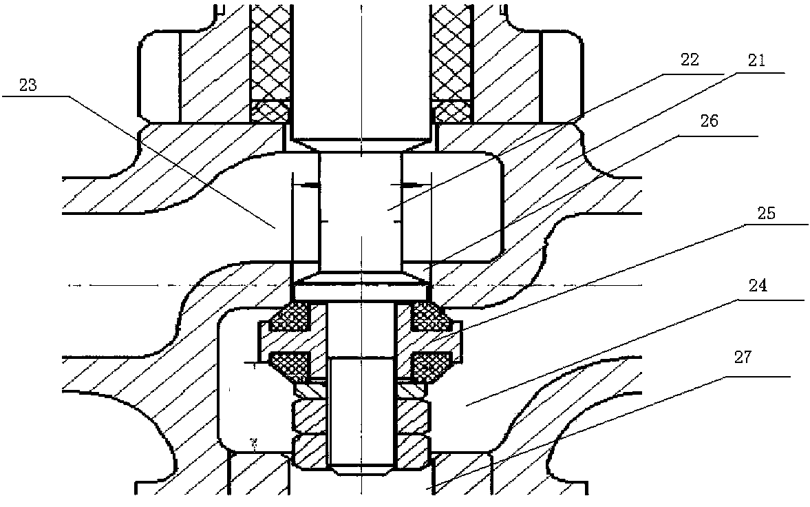
technical field [0001] The invention relates to a valve group, in particular to a plug-in integrated valve group and its working method. Background technique [0002] At present, shut-off valves are often used individually, and generally only have the function of switching on and off a single flow channel, and cannot simultaneously switch on and off multiple flow channels, let alone confluence of multiple flow channels; [0003] Existing commonly used cut-off valves (such as figure 1 Shown): Generally, it has the upper port of the valve, the lower port of the valve, the valve core, and the valve stem. The sealing cone surface between the upper and lower ports of the valve fits and seals the valve core. When the valve is closed, the valve stem has an upward pull on the valve core. When the valve is opened, the valve stem has a downward thrust on the valve core. The tightness of the valve core The nut is subject to variable load for a long time and is easy to loosen. At the...

Claims


Application Information

Patent Timeline
Patent Type & Authority Patents(China)
IPC IPC(8): F16K11/22F16K27/02F16K1/00
CPCF16K1/00F16K11/22F16K27/0263
Inventor 黄秀华江杰江志钧
Owner JIANDE XINANJIANG PNEUMATIC COMPONENT CO LTD
Learn More