Method for dynamically controlling reflection spectrum bandwidth of guided-mode resonance filter

A guided-mode resonance and filter technology, which is applied in the fields of optical communication and micro-electromechanical systems, can solve problems such as the size of a single spectral bandwidth and the dynamic adjustment of the spectral bandwidth of a guided-mode resonance filter.

Active Publication Date: 2016-07-13
JIANGNAN UNIV
View PDF7 Cites 8 Cited by
  • Summary
  • Abstract
  • Description
  • Claims
  • Application Information

AI Technical Summary

Problems solved by technology

The above method starts with changing the structural parameters of the grating layer or film layer, and can only design a guided-mode resonant filter with a specific bandwidth for specific applica

Method used


Image

  • Method for dynamically controlling reflection spectrum bandwidth of guided-mode resonance filter
  • Method for dynamically controlling reflection spectrum bandwidth of guided-mode resonance filter
  • Method for dynamically controlling reflection spectrum bandwidth of guided-mode resonance filter

Examples


Embodiment 1

[0020] Embodiment 1 Designing a Guided Mode Resonant Filter Using a Coupled Grating Structure

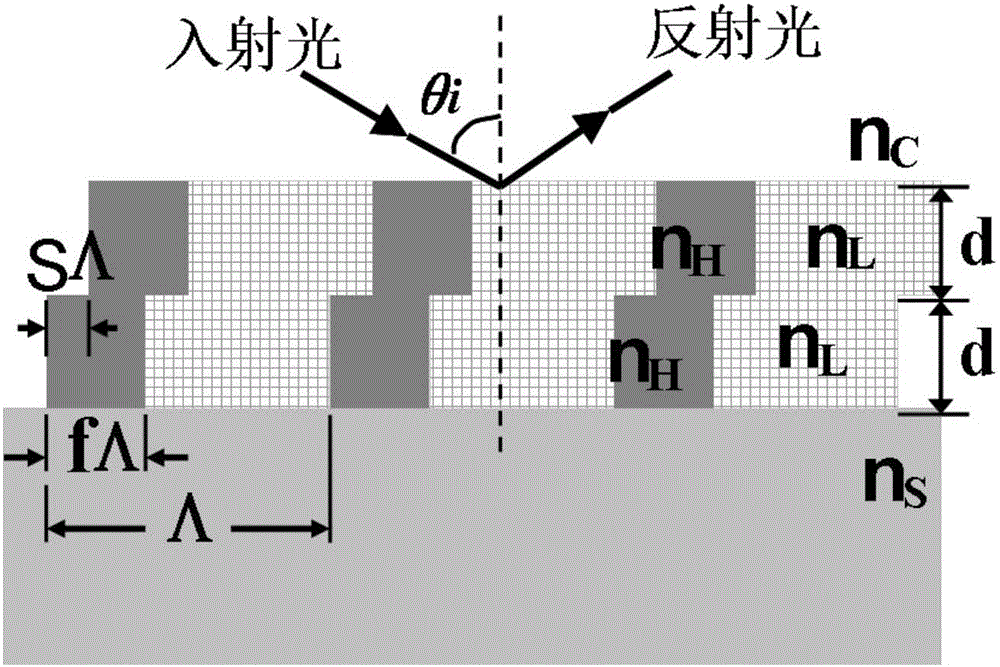
[0021] A guided-mode resonant filter is designed by using a coupling grating structure. The coupling grating is composed of two subwavelength gratings stacked up and down with one-half the thickness of the dummy layer. For TM polarized incident light, at the Brewster angle Nearby, the electromagnetic field coupling between the upper and lower two gratings is changed by controlling the relative lateral movement of the two gratings at the micro / nano level, so as to realize the dynamic regulation of the reflection spectral bandwidth of the guided mode resonant filter.

[0022] The design wavelength and material of the filter can be selected according to actual conditions. For TM polarization, select the design wavelength λ = 650nm, using HfO 2 and SiO 2 Two high and low refractive index materials, the refractive indices are: n H = 1.98, n L = 1.46. The incident medium is air n c ...

Embodiment 2

[0023] Embodiment 2 Dynamically adjust the bandwidth of the guided-mode resonant filter based on the coupling grating structure

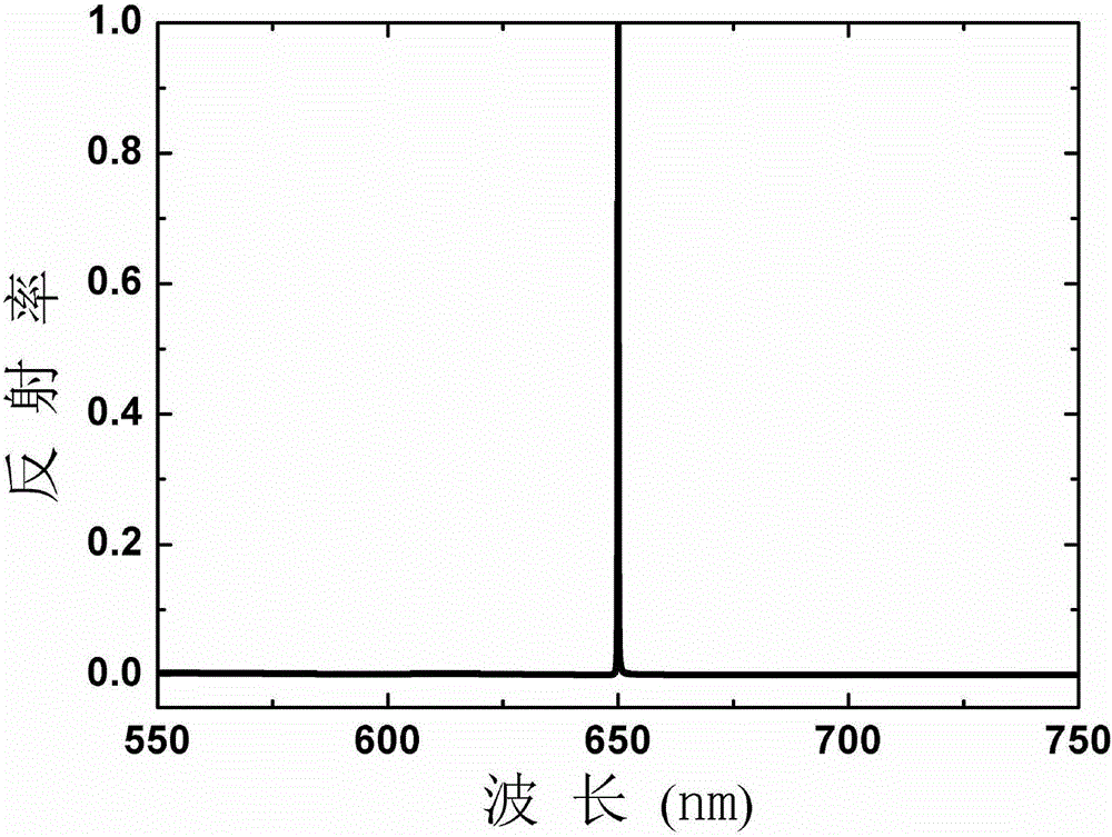
[0024] Based on the coupling grating structure design of the guided mode resonant filter in Example 1, the reflection filter spectrum curve of the guided mode resonant coupling grating is calculated by vector diffraction theory, and obtained figure 2 From the calculation results, it can be seen that due to the Brewster anti-reflection effect of TM polarization, in the 200nm wavelength range near the design wavelength of 650nm, the sideband reflectance of the filter is lower than 5‰, and the guided mode resonance reflection filter performance superior.

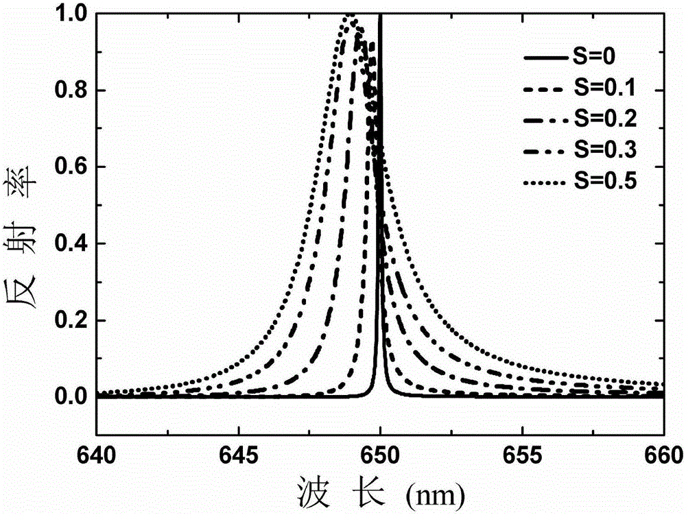
[0025] exist figure 2 Under the parameter condition of , select different grating traversing coefficient S, for example, S is 0.1, 0.2, 0.3, 0.5 respectively, and use vector diffraction theory to calculate the reflection spectrum curve of the guided-mode resonant coupling grating, and get image ...

Embodiment 3

[0026] Example 3 fine-tuning the incident angle to compensate for peak wavelength drift caused by grating traverse

[0027] When the coupling grating based on the embodiment 2 moves laterally, the equivalent refractive index of the coupling grating will change slightly, resulting in a slight shift of the peak position of the filter as S changes. In Example 2, the incident angle θ i=55.59°, when S=0, the peak of the coupling grating corresponds to the design wavelength of 650nm, but when S changes, the peak wavelength will slightly deviate from the design wavelength, for example, if S is 0.1, 0.2, 0.3, 0.5, the peak positions are 649.7nm and 649.3nm respectively , 648.9nm, 649.1nm. For the peak wavelength shift phenomenon caused by the change of S, the compensation for the peak wavelength shift can be realized by fine-tuning the incident angle.

[0028] For example, for S=0.1, use vector diffraction theory to calculate the relationship between filter reflectivity and incident...


PUM


Abstract

The invention discloses a method for dynamically controlling the reflection spectrum bandwidth of a guided-mode resonance filter and belongs to the fields of optical communication and micro electro mechanical systems. A coupling grating provided by the invention is composed of double equivalent grating bodies with the thickness one half of the thickness of an absentee layer and stacked vertically, for TM polarized incident light, structural magnetic field distribution is changed nearby a Brewster angle by controlling micro/nanoscale relative lateral movement between the two grating bodies, and continuous control of the reflection spectrum bandwidth of the guided-mode resonance filter is achieved. In the lateral movement process of the grating bodies, a peak wavelength shift phenomenon caused by the relative lateral movement between the grating bodies is not obvious, but the reflection spectrum bandwidth changes remarkably, and excellent anti-reflection filtering characteristics of the filter are kept when the two grating bodies produce the relative lateral movement. By finely adjusting an incidence angle, reflection peak shift caused by the relative lateral movement of the two grating bodies can be compensated.

Description

technical field [0001] The invention relates to a method for dynamically regulating the reflection spectrum bandwidth of a guided-mode resonant filter, in particular to a method for dynamically regulating the reflection spectrum bandwidth of a guided-mode resonant filter by using a coupling grating, belonging to the fields of optical communication and micro-electromechanical systems. Background technique [0002] Guided mode resonant filter is an optical element that utilizes guided mode resonance effect to achieve resonance filtering. This type of filter requires less film layers and has superior filtering performance. It is used in laser high reflection systems, polarization systems, optical modulators and biological Sensing and other aspects have important application value. In practical applications, the size of the spectral bandwidth is an important performance index of the filter. In order to effectively control the spectral bandwidth of the guided-mode resonant filte...

Claims


Application Information

Patent Timeline
IPC IPC(8): G02B5/20
CPCG02B5/203
Inventor 桑田王跃科李俊浪周健宇王睿
Owner JIANGNAN UNIV
Why Eureka
Try Eureka