Knife-shaped fuse switch

A technology of knife fuse switch and fuse, which is applied in the field of switches, can solve the problems of inconvenient installation of knife fuse switch, easy breakdown of contacts, burning of human body, etc., and achieve the effect of safe and reliable use, not easy to arc, and guarantee safety

Inactive Publication Date: 2016-07-13
TIANJIN BOJIU ELECTROMECHANICAL EQUIP
View PDF0 Cites 0 Cited by
  • Summary
  • Abstract
  • Description
  • Claims
  • Application Information

AI Technical Summary

Problems solved by technology

[0002] Knife fuse switch is the simplest and most widely used low-voltage electrical appliance among hand-controlled electrical appliances. It is a single control switch for closing and disconnecting. Contact, so as to realize the closure of the circuit. When the handle is dialed down, the dynamic and static contacts will be disconnected, and the circuit will be disconnected. During use, when the load power is too large, the current flowing through the fuse will cause the fuse to heat up. The fuse plays the role of protecting the circuit. After troubleshooting, replace the fuse and continue to use it. It is generally used in the main line of the lighting circuit. The knife fuse switch of the prior art meets the needs of the market to a certain extent, but The installation of the existing knife fuse switch is very inconvenient, and the contacts are easy to break down and generate arcs, which will cause burns to the human body

Method used


Image

  • Knife-shaped fuse switch
  • Knife-shaped fuse switch

Examples


Embodiment Construction

[0015] For further illustrating the present invention, now cooperate with accompanying drawing to elaborate:

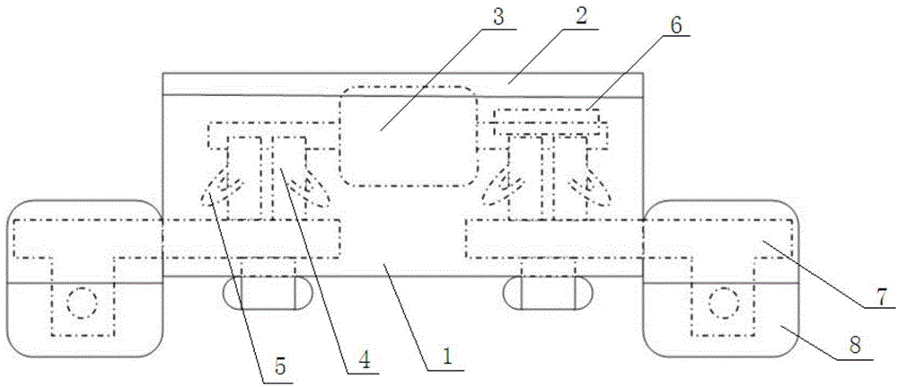
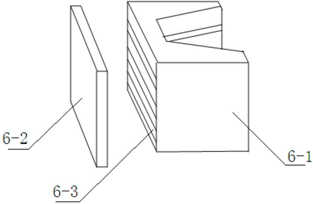
[0016] Such as Figure 1-2 As shown, the knife fuse switch includes a housing 1, a back plate 2, a fuse part 3, a static contact 4, a spring 5, an arc chute 6, a fitting 7 and a fitting sheath 8, and the housing 1 and The back plate 2 is matched and fixed so that the housing 1 forms an airtight space. The hardware 7 is plugged and fixed on both sides of the housing 1. The parts of the hardware 7 exposed outside the housing 1 are provided with through holes, which facilitate ventilation and heat dissipation. Function, the part of the metal fitting 7 exposed outside the casing 1 is set in the fitting sheath 8, and the fitting sheath 8 is movably connected with the casing 1, and the part of the fitting 7 placed inside the casing 1 is in contact with the static fitting. The contacts 4 are fixedly connected, the spring 5 is a square spring 5 with a ring structure, and the...


PUM


Abstract

The invention provides a knife-shaped fuse switch, which comprises a shell, a back plate, a fuse component, a static contact, a spring, an arc chute and an armour clamp. The shell and the back plate are fixedly matched with each other to form a closed space in the shell. The armour clamp is fixedly inserted at the two sides of the shell. The part of the armour clamp, exposed out of the shell, is provided with a through hole. The part of the armour clamp, positioned inside the shell, is fixedly connected to the static contact. The spring is in the form of a square spring of an annular structure. The spring is tightly nested at the periphery of the static contact. The arc chute is fixedly connected with the sidewall of the shell and is arranged right above the static contact. The fuse component is fixed onto the back plate in a snap-fitted manner. Meanwhile, the fuse component, the static contact and the arc chute are in contact with one another in a plug-in manner. The knife-shaped fuse switch is dustproof, rainproof, and safe and reliable to use. The live-line operation of the knife-shaped fuse switch is enabled, so that the arc is less likely to occur. The safety of the maintenance personnel is ensured. Meanwhile, all part of the knife-shaped fuse switch are convenient in replacement. The knife-shaped fuse switch has important application value.

Description

technical field [0001] The invention relates to a switch, in particular to a knife fuse switch. Background technique [0002] Knife fuse switch is the simplest and most widely used low-voltage electrical appliance among hand-controlled electrical appliances. It is a single control switch for closing and disconnecting. Contact, so as to realize the closure of the circuit. When the handle is dialed down, the dynamic and static contacts will be disconnected, and the circuit will be disconnected. During use, when the load power is too large, the current flowing through the fuse will cause the fuse to heat up. The fuse plays the role of protecting the circuit. After troubleshooting, replace the fuse and continue to use it. It is generally used in the main line of the lighting circuit. The knife fuse switch of the prior art meets the needs of the market to a certain extent, but The installation of the existing knife fuse switch is very inconvenient, and the contacts are easy to b...

Claims


Application Information

Patent Timeline
Patent Type & Authority Applications(China)
IPC IPC(8): H01H9/04H01H9/34
Inventor 宗立民雷正香刘志远
Owner TIANJIN BOJIU ELECTROMECHANICAL EQUIP
Why Eureka
Try Eureka