Ball frame structure with reduced volume

A technology of reducing volume and ball racks, applied in the field of ball racks, can solve problems such as the danger of structural finger pinching, and achieve the effects of reduced volume, more balls to accommodate, and strong practicability

Inactive Publication Date: 2018-07-27
陈登癸
View PDF7 Cites 0 Cited by
  • Summary
  • Abstract
  • Description
  • Claims
  • Application Information

AI Technical Summary

Problems solved by technology

[0003] On the other hand, when the existing connecting columns are expanded to the required size, it is necessary to position them at a distance to avoid accidents of self-folding, such as figure 2 As shown, it is a common turning positioning rod 19, and its turning positioning rod 19 includes two rod bodies 191, 192, one end of which is pivotally connected. The positioning block 1911 is provided with a positioning groove 1921, so that the positioning block 1911 of the two rod bodies 191, 192 is snapped toward the positioning groove 1921 to achieve the purpose of positioning, but its structure is quite easy to cause the danger of pinching fingers. Need for improvement

Method used


Image

  • Ball frame structure with reduced volume
  • Ball frame structure with reduced volume
  • Ball frame structure with reduced volume

Examples


Embodiment Construction

[0028] The present invention will be described in further detail below in conjunction with the accompanying drawings.

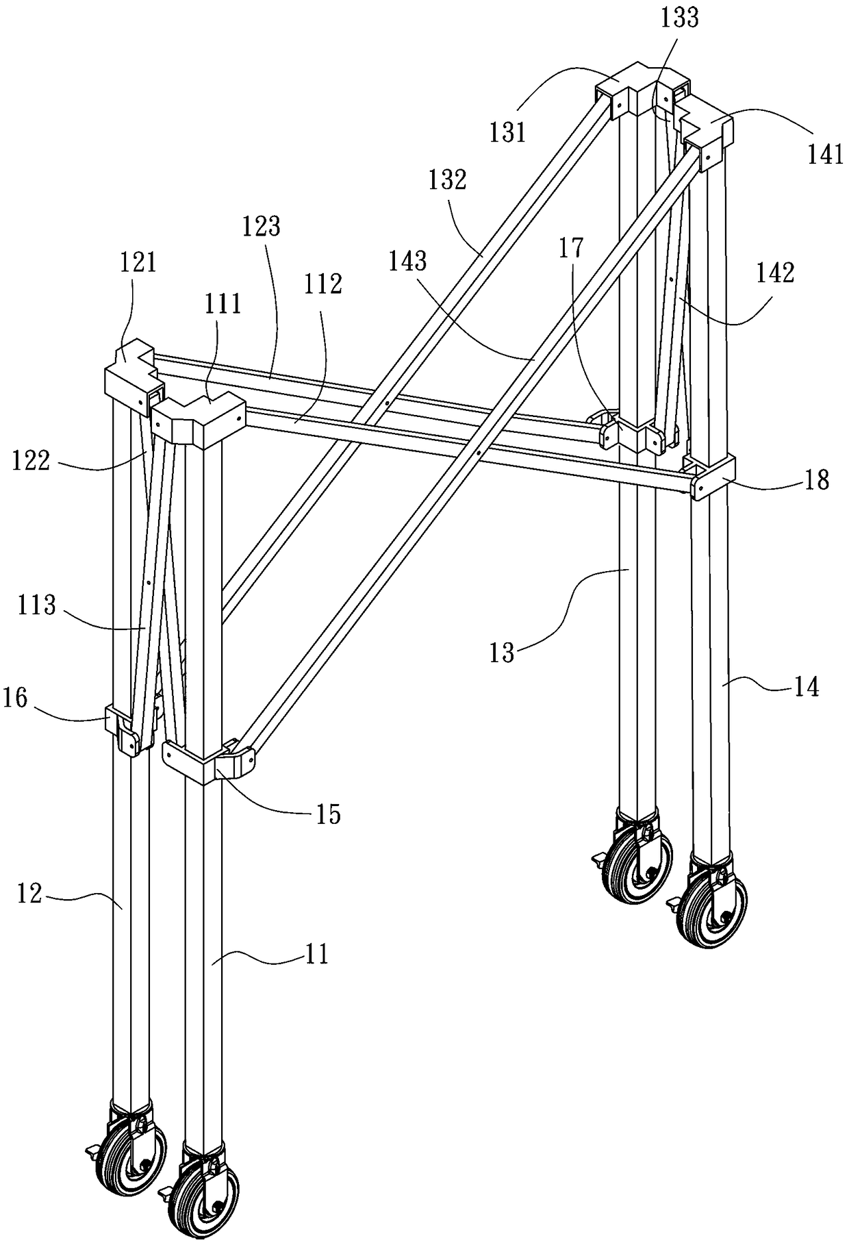
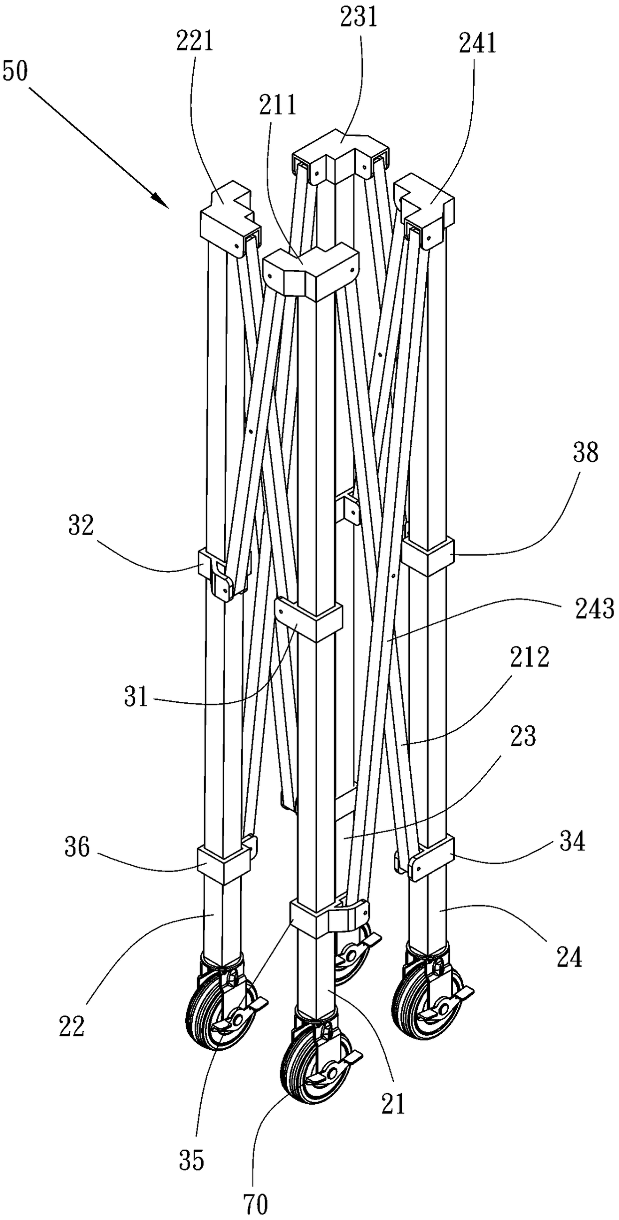
[0029] Such as Figure 1-6 As shown, the present invention provides a ball frame structure with reduced volume, comprising:

[0030] The pillars are respectively the first to fourth pillars 21, 22, 23, 24;

[0031] The several top sleeve parts are respectively the first to fourth top sleeve parts 211, 221, 231, 241, and the top ends of the first to fourth cylinders 21, 22, 23, 24 are respectively fixed with the first to fourth top sleeve parts. 211, 221, 231, 241;

[0032]Several connecting columns with the same or different lengths are respectively the first to the eighth connecting columns 212, 213, 222, 223, 232, 233, 242, 243, and the first top sleeve portion 211 is pivotally equipped with a first connecting column 212 and a One end of the second connecting column 213, the second top sleeve part 221 is pivoted with one end of a third connecting column ...


PUM


Abstract

The invention discloses an improved ball rack structure of reduced size.The improved ball rack structure comprises four supporting column bodies and eight connecting columns, wherein every two equal-length connecting columns form a group and are staggered and connected in a pivoted mode to form a connecting column group, and the equal-length connecting column groups are oppositely arranged and are connected to ejecting sleeve portions fixed on the four supporting column bodies or sliding sleeves slidably arranged on the four supporting column bodies in a pivoted mode.The bottom end of each connecting column is arranged on the corresponding independent sliding sleeve in a pivoted mode, so that the eight connecting columns are provided with the eight matched sliding sleeves for pivoted connection of the columns.Therefore, even if the eight connecting columns are different in length, an unfolded ball rack can be square or rectangular, the number of accommodated balls can be larger, and the best closing-up effect of complete closing up can be reached during closing up of the ball rack.

Description

technical field [0001] The present invention provides the technical field of a ball stand, especially to provide a ball stand structure with a reduced volume in technology, which can match a connecting post with a sliding sleeve, so that when the connecting posts on two adjacent sides are not equal in length , can still achieve the best performance reduction in size. Background technique [0002] Such as figure 1 As shown, it is an existing collapsible and reduced-volume ball rack. The existing collapsible and reduced-volume ball rack includes a front, a rear, a left side, and a right side, each of which is provided with a first To the four cylinders 11, 12, 13, 14, the first to the four cylinders 11, 12, 13, 14 tops are respectively fixed with a first to four top cover parts 111, 121, 131, 141, and the first top cover part 111 pivots One end of a first connecting column 112 and a second connecting column 113 is established, the second top cover part 121 is pivotally provi...

Claims


Application Information

Patent Timeline
Patent Type & Authority Patents(China)
IPC IPC(8): A63B71/00
CPCA63B71/0036
Inventor 陈登癸
Owner 陈登癸
Why Eureka
Try Eureka