Rotary jet mixing low-energy consumption flotation equipment driven by utilizing ore pulp

A low energy consumption, jet flow technology, applied in flotation, solid separation, etc., can solve the problems of particle shedding, high energy consumption, and affecting flotation effect, and achieve the effect of reducing energy loss

Active Publication Date: 2016-07-20
滦平县小营乡利民矿业有限公司
View PDF13 Cites 3 Cited by
  • Summary
  • Abstract
  • Description
  • Claims
  • Application Information

AI Technical Summary

Problems solved by technology

Since the non-mechanical stirring flotation machine has no stirring mechanism, the pump is used to provide energy for the pulp, and the jet flow and collision of the pulp are dispersed to absorb enough air. The disadvantage is that it needs a matching pump and consumes a lot of energy.
In addition, since the non-mechanical agitation flotation machine needs to ensure sufficient ore flow and suction capacity, the flow field in the flotation tank is often excessively turbulent, causing the mineralized particles to fall off during the flotation process, thereby affecting the flotation effect

Method used


Image

  • Rotary jet mixing low-energy consumption flotation equipment driven by utilizing ore pulp
  • Rotary jet mixing low-energy consumption flotation equipment driven by utilizing ore pulp
  • Rotary jet mixing low-energy consumption flotation equipment driven by utilizing ore pulp

Examples


Embodiment Construction

[0042] For ease of understanding, combined here Figure 1-9 , the specific embodiments of the present invention are further described as follows:

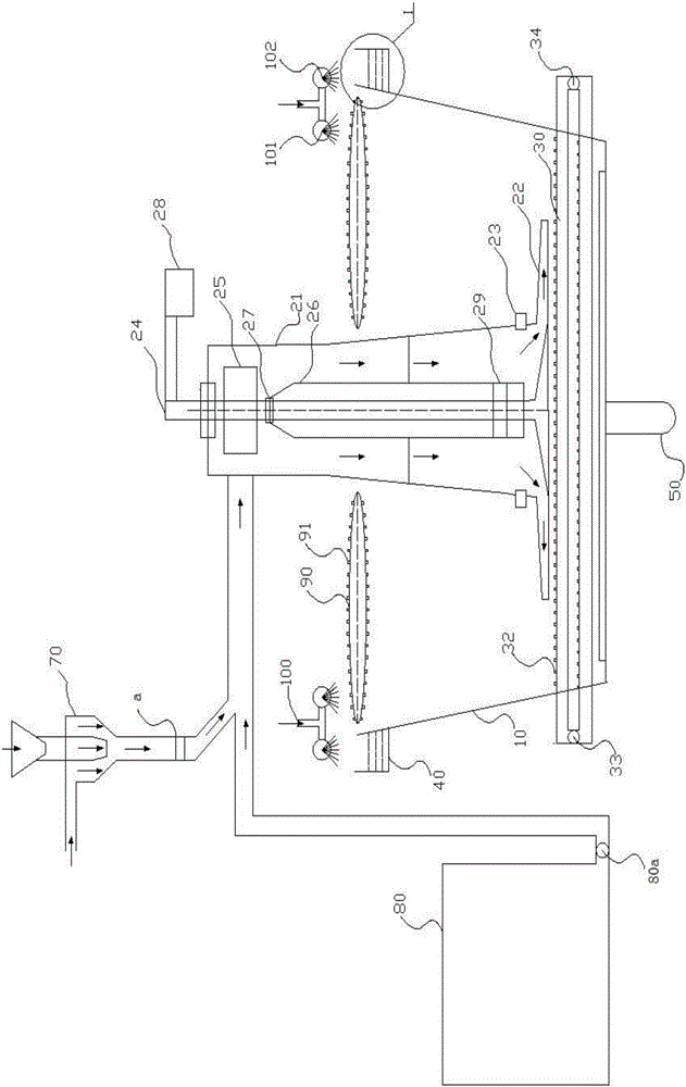
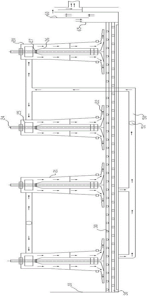
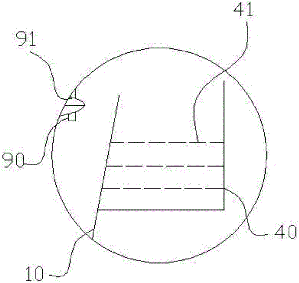
[0043] The specific components of the present invention are divided into several modules, including: feeding buffer tank 80, annular nozzle jet device 70, flotation tank 10, jet-driven agitator 20, microbubble generating bed 30, concentrate collection tank 40, Circulating foam scraping group 90, clean water spray assembly 100 and tailings box. Describe them one by one below:

[0044] 1. Flotation feeding buffer barrel

[0045] Its structure is as figure 1 As shown, the overall structure is in a cylindrical barrel, and the slurry inside is transported to the first group of mixing units by the feeding pump 80a through the feeding main pipeline, and the two jet-driven agitators 20 of the first group of mixing units are driven to work.

[0046] 2. Ring nozzle jet device

[0047] The ore slurry in the flotation feeding buffer tank ...


PUM


Abstract

The invention relates to the field of coal slime flotation treatment, in particular to rotary jet mixing low-energy consumption flotation equipment driven by utilizing ore pulp. The rotary jet mixing low-energy consumption flotation equipment at least comprises a flotation groove, wherein jet driving mixers are arranged in the flotation groove; each jet driving mixer comprises a driving turbine and a swirl jet mixing rotor which are separately connected to the upper part and the lower part of a rotary shaft, and the rotary shaft rotates under the joint action of driving force of the corresponding driving turbine and nozzle jet reactive force; the residue power of conveyed ore pulp is fully utilized, so that flotation mixing in the groove is realized; the rotary jet mixing low-energy consumption flotation equipment further comprises micro foam generation beds which are formed by micro foam generation pipes and are divided into an upper layer and a lower layer; the micro foam generation beds are arranged in a staggered manner and are not coincided with each other; micro foam generation holes are uniformly distributed in each micro foam generation pipe; and the left end and the right end of the micro foam generation beds are separately provided with a gas pipeline and a cleaning water pipeline. The rotary jet mixing low-energy consumption flotation equipment has the advantages that mixing energy consumption is low; the micro foam flotation effect is good; no flotation dead zones exist in the flotation groove; a foam layer is more stable; the work efficiency and the flotation effect both can be effectively ensured.

Description

technical field [0001] The invention relates to the field of coal slime flotation treatment, in particular to a low-energy-consumption flotation equipment driven by ore pulp using rotating jet stirring. Background technique [0002] Flotation is the most important interface separation method, usually used for the separation of -0.5mm coal slime, and it is the only effective separation method for -0.1mm coal slime. There are many types of flotation machines, and the differences are mainly reflected in the inflation method and the structure of the inflation stirring device. At present, the most widely used classification method is to divide flotation machines into two categories: mechanical agitation type and non-mechanical agitation type according to the different aeration and agitation methods. The mechanical agitation flotation machine can refer to the Chinese patent announcement number "CN201711220U" named "mechanical agitation flotation machine", which uses the stirring ...

Claims


Application Information

Patent Timeline
Patent Type & Authority Applications(China)
IPC IPC(8): B03D1/16
CPCB03D1/16Y02P70/10
Inventor 周伟朱金波闵凡飞刘令云韩有理白雪杰张祥张雪菲翟启超
Owner 滦平县小营乡利民矿业有限公司
Why Eureka
Try Eureka