Full-automatic lifting fixture

A fully automatic, fixture technology, applied in the direction of clamping, manufacturing tools, supports, etc., can solve problems such as degree of automation, achieve the effect of high degree of automation, easy to popularize and use, and achieve the effect of horizontal position

Inactive Publication Date: 2016-07-20
黄斌
View PDF6 Cites 5 Cited by
  • Summary
  • Abstract
  • Description
  • Claims
  • Application Information

AI Technical Summary

Problems solved by technology

The degree of automation of fixtures in the prior art needs to be further improved

Method used


Image

  • Full-automatic lifting fixture
  • Full-automatic lifting fixture
  • Full-automatic lifting fixture

Examples


Embodiment Construction

[0031] In order to make the object, technical solution and advantages of the present invention clearer, the present invention will be further described in detail below in conjunction with the accompanying drawings and embodiments.

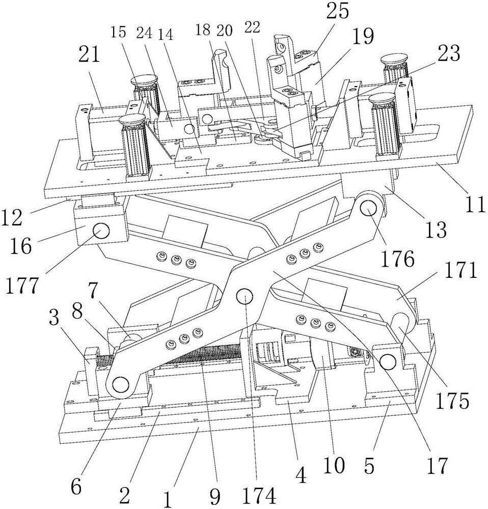
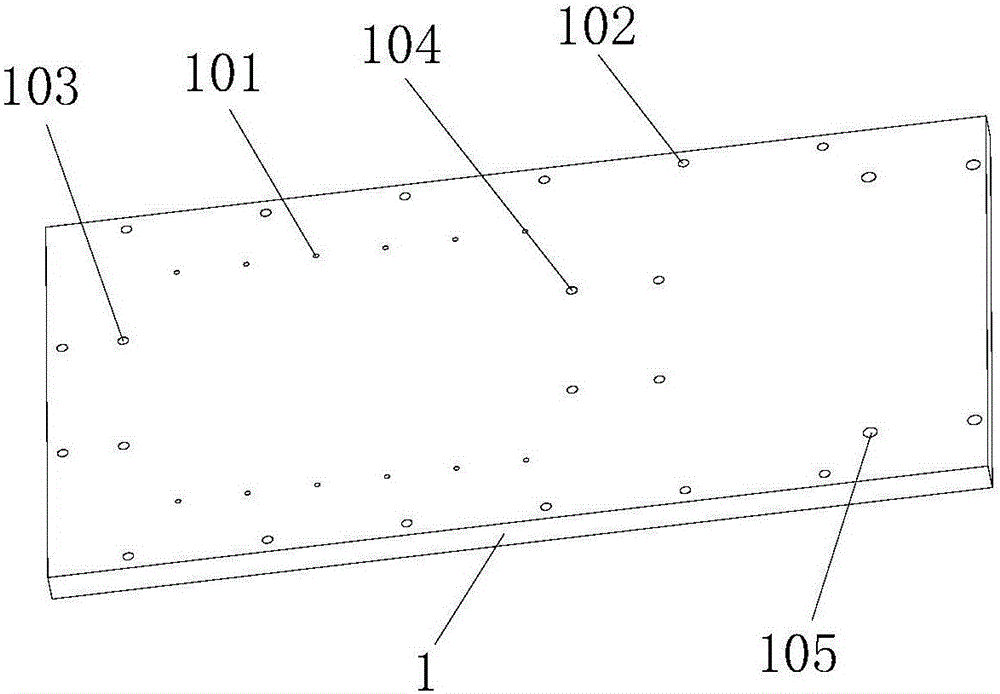
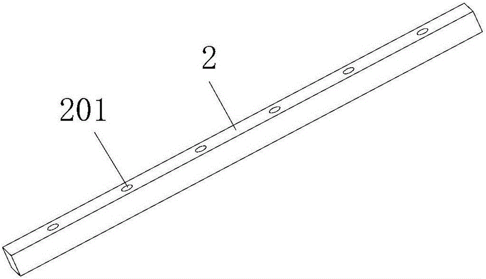
[0032] see Figure 1-Figure 15 , the full-automatic lifting fixture includes a base 1, two slide rails A2 installed on the base 1, a support block 3 installed on the base 1, and a support seat installed on the base 1 4. Two fixed blocks 5 installed on the base 1; a sliding seat A6 is installed between the two slide rails A2, and a silk shaft 7 passes through the sliding seat A6, and the A screw shaft seat 8 is installed on the screw shaft 7, and a leading screw 9 is passed through in the screw shaft seat 8, and one end of the leading screw 9 is installed on the supporting block 3, and the other end of the leading screw 9 passes through the supporting seat 4 and The output shaft of the motor 10 is connected through a coupling; the fully automatic l...


PUM


Abstract

The invention discloses a full-automatic lifting fixture. The full-automatic lifting fixture comprises a base, two slide rails A, a supporting block, a supporting base and two fixing blocks. A slide base A is installed between the two slide rails A. A screw shaft is arranged on the slide base A in a penetrating mode. A screw shaft base is installed on the screw shaft. A screw rod is arranged in the screw shaft base in a penetrating mode. One end of the screw rod is installed on the supporting block, and the other end of the screw rod penetrates through the supporting base and is connected with an output shaft of a motor through a coupling. The full-automatic lifting fixture further comprises a top plate, two side rails B, two fixed connecting blocks, a convex plate and an air cylinder supporting base. A slide base B is installed between the two slide rails B. A lifting adjusting mechanism is installed between the base and the top plate. Three slide rails C are installed on the convex plate. Slide clamping bases are installed on the slide rails C. A movable rotating shaft is arranged in the convex plate in a penetrating mode. A triangular rotating plate is installed on the movable rotating shaft. An air cylinder is installed at one end of the air cylinder supporting base, and the slide clamping bases are pushed to slide on the slide rails C. A clamping head is installed at the upper end of each slide clamping base through a bolt.

Description

technical field [0001] The invention relates to the technical field of clamp structures, in particular to a fully automatic lifting clamp. Background technique [0002] With the advancement of science and technology, it has become an inevitable trend to replace manual operation with manipulators in the production process, especially when the working environment is harsh and dangerous. Replacing manual operations with manipulators not only ensures personal safety, but also improves Improve work efficiency and avoid damage caused by manual operation errors. The degree of automation of the clamps in the prior art needs to be further improved. Contents of the invention [0003] The purpose of the present invention is to provide a fully automatic lifting fixture in order to overcome the deficiencies of the prior art. [0004] The present invention is realized through the following technical solutions: [0005] A fully automatic lifting fixture, comprising a base, two slide r...

Claims


Application Information

Patent Timeline
IPC IPC(8): B23Q3/00
CPCB23Q3/00
Inventor 黄斌
Owner 黄斌
Why Eureka
Try Eureka