
Injection mold ejection device for automobile bumpers

A technology for automobile bumpers and injection molds, which is applied in the field of automobile injection molding parts. It can solve the problems such as the difficulty of returning the wedge-shaped slider and ejector plate, and achieve the effect of smooth ejection and return process.

Inactive Publication Date: 2016-07-20
CHONGQING DAFO PLASTIC
View PDF1 Cites 2 Cited by
  • Summary
  • Abstract
  • Description
  • Claims
  • Application Information

AI Technical Summary

Problems solved by technology

[0005] Aiming at the situation that the wedge-shaped slider and the ejector plate in the existing injection mold ejection device are difficult to return, the invention provides an injection mold ejection device with a smoother ejection and return process.

Method used


Image

  • Injection mold ejection device for automobile bumpers
  • Injection mold ejection device for automobile bumpers
  • Injection mold ejection device for automobile bumpers

Examples


Embodiment 1

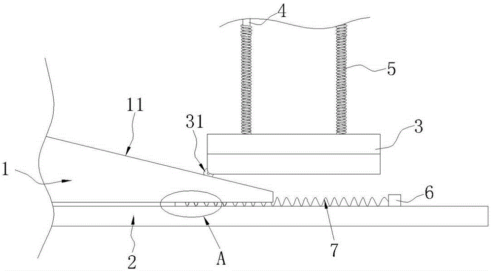
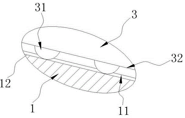
[0019] Embodiment 1: as figure 1 , figure 2 As shown, an injection mold ejection device for an automobile bumper includes a wedge-shaped slider 1 and an ejector plate 3 positioned at the front side of the inclined surface 11 of the wedge-shaped slider. Rail 2 and thimble plate 3 are provided with a number of thimbles 5 for ejecting the plastic parts of the bumper. The thimble 5 is covered with a thimble return spring 5; since rolling friction is smoother than sliding friction, the thimble plate 3 A roller 31 that rolls relative to the wedge-shaped slider slope 11 is set on the top, and the wedge-shaped slider slope 11 is provided with a groove 12 (see Figure 4 ), so that the roller 31 can roll in the groove 12, and of course the groove 12 can also be replaced by a protrusion, so that the rollers 31 can be distributed on both sides of the protrusion.

[0020] In order to enable the wedge-shaped slider 1 to return to the initial position after completing the process of eject...

Embodiment 2

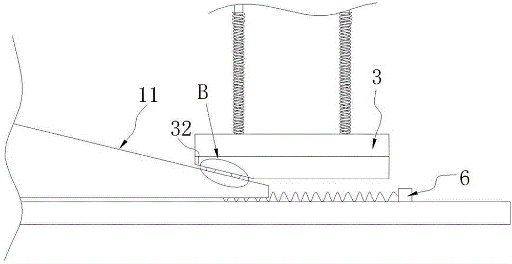
[0023] Such as image 3 , Figure 4 As shown, the difference between this embodiment and Embodiment 1 is that the ejector plate 3 is provided with a reverse wedge-shaped surface 32 matching the wedge-shaped slider slope 11, and the pulley 31 is fixed on the reverse wedge-shaped surface 32, so that Further pulleys 31 can be provided on the wedge surface 32 . In order to further improve the stability of rolling friction, the pulley 31 is specifically a pulley block composed of a plurality of single pulleys, which can make the mutual movement between the wedge-shaped slider 1 and the ejector plate 3 smoother.


PUM


Abstract

The invention discloses an injection mold ejection device for automobile bumpers, and belongs to the technical field of injection molding parts of automobiles. The injection mold ejection device is used for solving the problem that existing injection mold ejection devices with the adjustable ejection distance are easily jammed in the return process. The injection mold ejection device comprises a wedge-shaped sliding block and an ejection pin plate located in front of an inclined surface of the wedge-shaped sliding block, a sliding rail accepting sliding of the wedge-shaped sliding block is arranged under the wedge-shaped sliding block, a plurality of ejection pins used for ejecting injection molds are arranged on the ejection pin plate, and ejection pin return springs are arranged on the outer sides of the ejection pins in a sleeving mode. The injection mold ejection device is characterized in that rolling wheels capable of rolling relative to the inclined surface of the wedge-shaped sliding block are arranged on the ejection pin plate, and the inclined surface of the wedge-shaped sliding block is provided with a groove or a protrusion part matched with the rolling wheels. According to the injection mold ejection device, the ejection process and the return process of the injection mold ejection device are smoother through rolling friction and improvements on a return device.

Description

technical field [0001] The invention belongs to the technical field of injection molding parts for automobiles, in particular to an improved injection mold ejector for automobile bumpers. Background technique [0002] The car bumper is a safety device that absorbs and eases external impact and protects the front and rear of the car body, and plays a role in protecting people and cars. With the development of the automobile industry, the automobile bumper, as an important safety device, is also on the road of innovation. At present, in addition to maintaining the original protective function, the front and rear bumpers of automobiles also need to pursue harmony and unity with the shape of the car body, and pursue their own lightweight. In order to achieve this purpose, the front and rear bumpers of cars use relatively common polyester and polypropylene plastics, the so-called plastic bumpers. [0003] In the manufacturing process of plastic bumpers, most of them now use inj...

Claims


Application Information

Patent Timeline
IPC IPC(8): B29C45/40
Inventor 李浩明
Owner CHONGQING DAFO PLASTIC
Learn More